Project 6
Here's a brief description of the circuit:
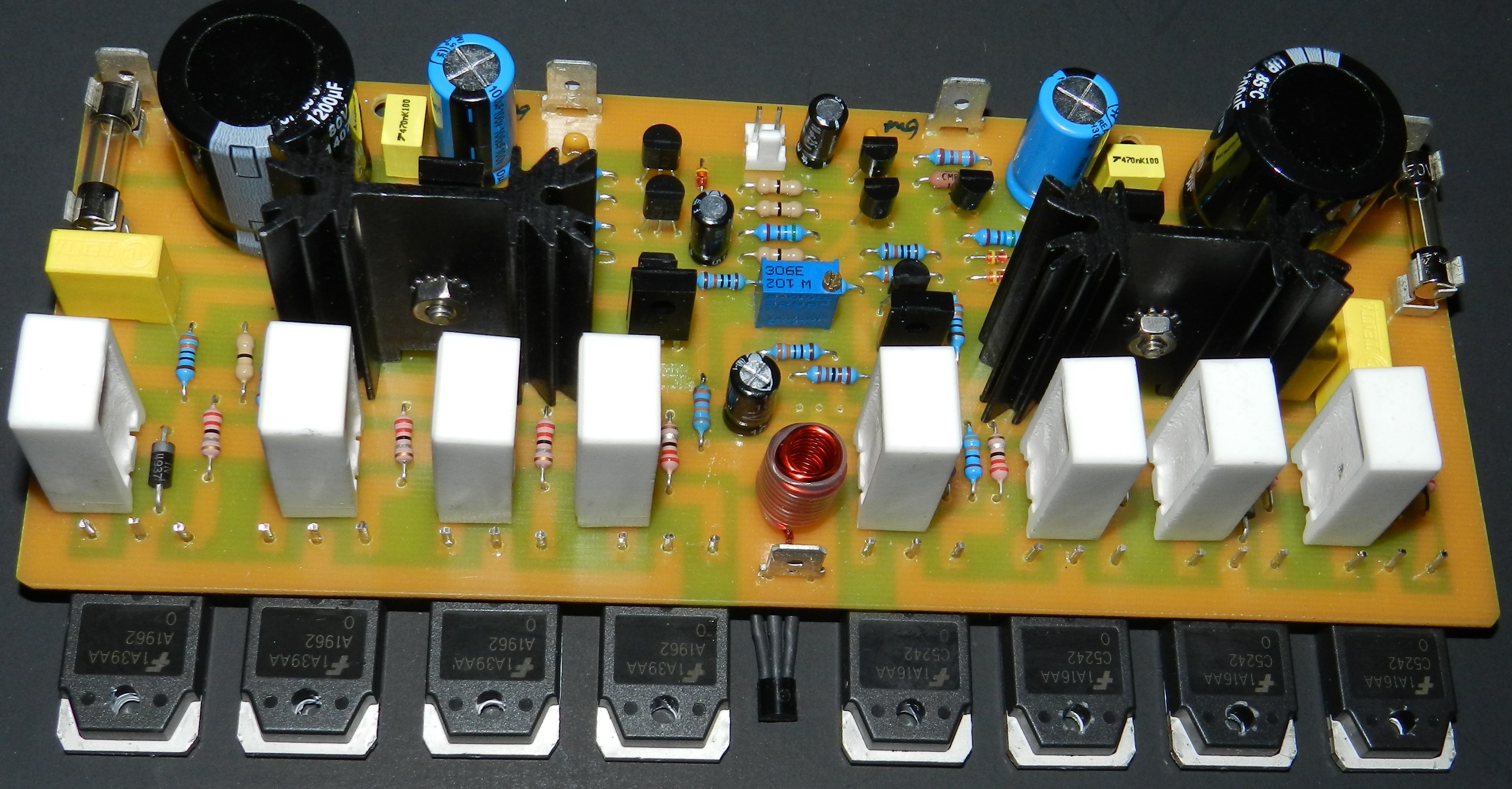
Project 6 is rated at 230W into 8 ohms load with a main power supply rails of ±65VDC. The input stage is a differential amplifier circuit consisting of Q1/Q2, current-mirrored by Q4/Q5 and current-sourced by Q3, D2 and D3. The output of the differential amplifier input stage is connected to the voltage amplifier stage Q7/Q9, loaded by a current-source circuit Q6/Q8 and high frequency stabilized by R10/C6. Q10 together with VR1 adjusts the bias current of the output stage. Q10 is populated off the PCB and attached to the project's aluminum bracket for thermal feedback. The output of the voltage amplifier stage drives a two-stage emitter follower power output stage drivers Q11/Q13 and Q12/Q14. The power output stage consists of full complementary emitter followers Q15 to Q22. L1, R41 and C16 are necessary for the stability of the amplifier at any loads. There should be a resistor in parallel with L1, a 4.7 Ω 2Watt resistor of SMT-type that can be populated on the bottom copper layer side of the PCB. The gain of the amplifier is determined by the ratio of R9 and R7 in series with C5.
If you plan to build this project, a Bill Of Materials (Project6 BOM), schematic diagram, PCB bottom copper and silkscreen parts placement layers are provided for free by request, as is, no warranty.
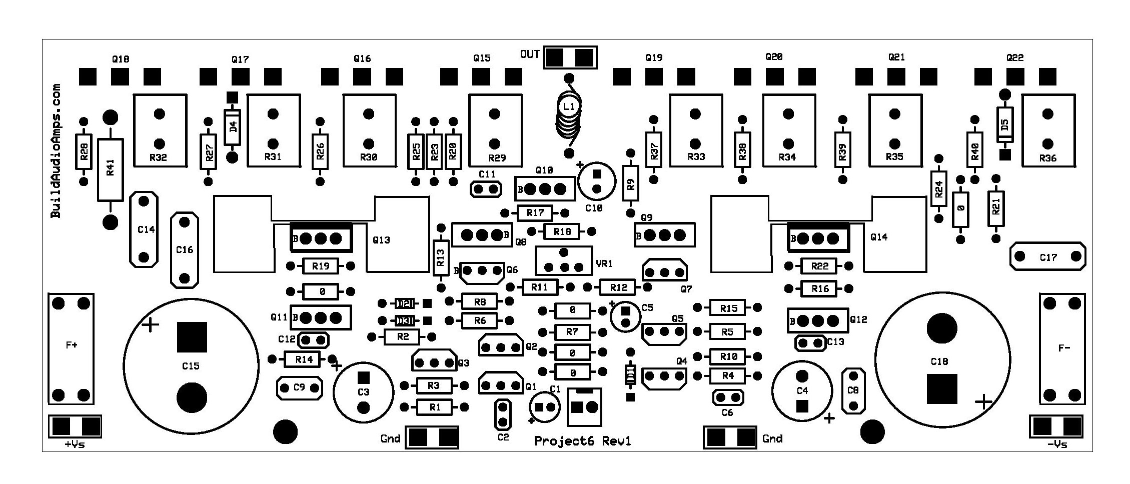
Silkscreen Parts Placement Layer of Project 6
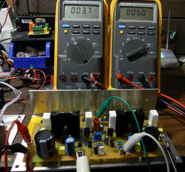
After completion of the printed circuit assembly, it is time to do some simple test and adjustment. Connect a shunt or shorting jumper at the input of the amplifier. Connect the DMMs as shown in next picture. For initial test, I will be using a ±30VDC power supply. The green and white test clips are connected to the DMM on the left of the picture. It reads 3.7mV; the DC offset voltage of the amplifier. The red and black test clips are connected to the DMM on the right. It reads 50mA, the idle current of the amplifier. It can be adjusted by turning VR1 clockwise. If you obtained different readings, switch the power supply OFF immediately and check for assembly errors, the usual stuff.
If you obtain the same DMM readings, you may proceed with music test and enjoy! If you prefer, the following test procedures will illustrate another method in adjusting the bias current of the amplifier.
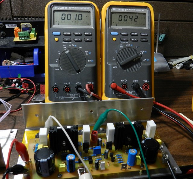
The white test clip is connected to the emitter of Q18 and green test clip connected to output of the amplifier and then both are connected to the DMM on the left, set to millivoltmeter function. Adjust VR1 clockwise to obtain +1mV. The red and black test clips on the fuse terminals are connected to the DMM set to milliammeter function and reads 42mA. This reading is dependent on your adjustment of VR1.
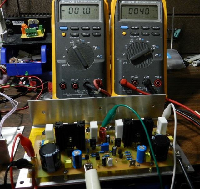
The white test clip is now moved to the emitter of Q22. Adjust VR1 clockwise to obtain -1mV. The millammeter on the fuse terminals reads 40mA. Therefore VR1 should be adjusted to read 41mA. After some period of time, the idle current willl rise and needs to be re-adjusted. If you intend to use a higher power supply voltage you may do so, at your own risk, as long as you don’t exceed the voltage rating of the onboard filter capacitors. The same adjustment procedures should be followed.
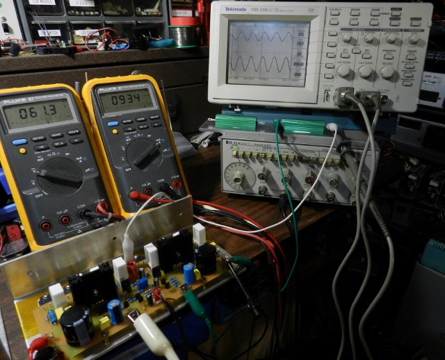
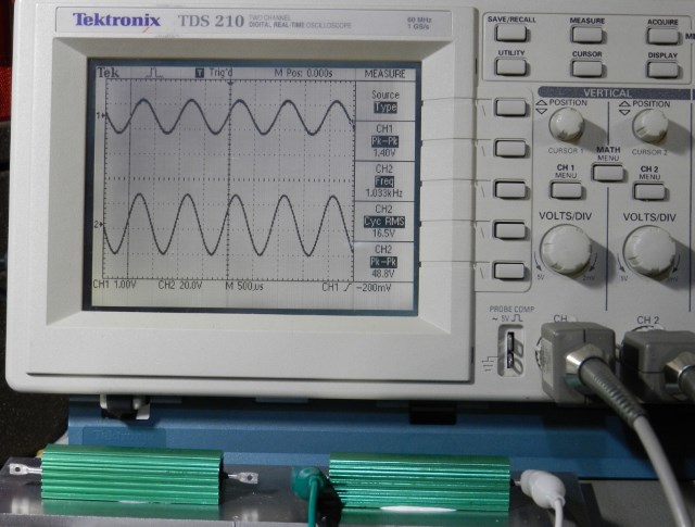
The following test procedure is optional. The DMM on left reads 61.3 volts (±30.65VDC) the voltage across the positive and negative power supply rails while DMM on right reads 934mA the current at V+ fuse terminals. The function generator is set at 1KHz about 1Vp-p sine wave output. The amplifier is loaded with an 8Ω 100Watt power resistor. The output of the amplifier just before clipping occurs, reads 48.8Vp-p or 16.5Vrms as shown in the oscilloscope.
The music it reproduced was in my opinion very good. I paired this project with the LM1036 tone control project.
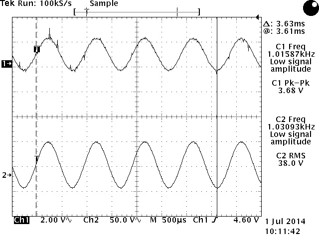
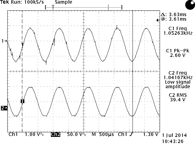
More test pictures, this time using a ±54VDC power supply and a Tektronix TDS520D oscilloscope. A 1KHz 3.68Vpp sine wave input signal produces about 38Vrms across an 8Ω/400W load or a power output of about 180Wrms. At 1KHz 2.6Vpp sine wave input signal produces about 39.4Vrms across an 8Ω load or a power output of about 194Wrms, just before clipping occurs.