Make Printed Circuit Boards
Make your own Printed Circuit Board (PCB)
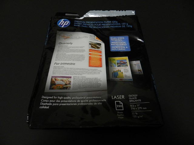
After you’ve made your PCB layout design, print a copy to a laser pinter using glossy presentation paper. I use this kind of presentation paper from HP on my Samsung ML2525W laser printer.
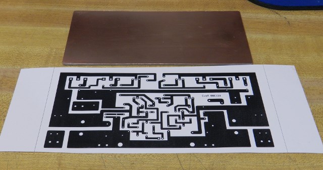
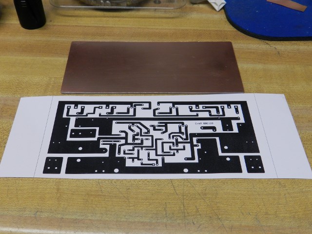
Prepare your copper board and printed layout. Clean copper board with 91% isopropyl alcohol.
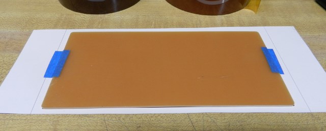
Tape the printed side of presentation paper facing the copper side of board.
You can use a laminating machine as the heat source but I prefer using a regular electric clothing iron, every home should have one. With the iron adjusted to maximum heat setting, carefully press the presentation paper for about 5 to 10 minutes depending on power wattage of iron. The profile of the layout can be seen from the opposite side of presentation paper that's the toner polymer being transferred to the copper board by heat.
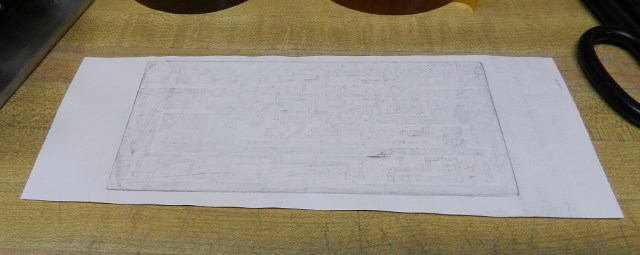
If you see that profile, then it is about time to carefully peel off the presentation paper from the copper board.
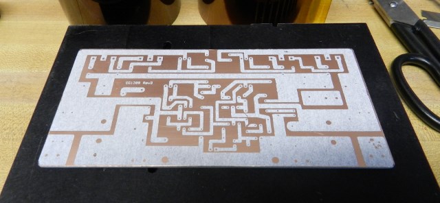
As you can see there are minor imperfections during the transfer, an easy fix is to use a fine point permanent marker to cover up missing etchant resists.

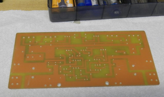
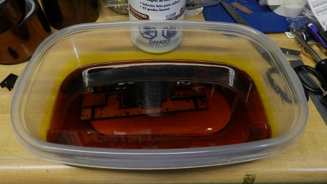
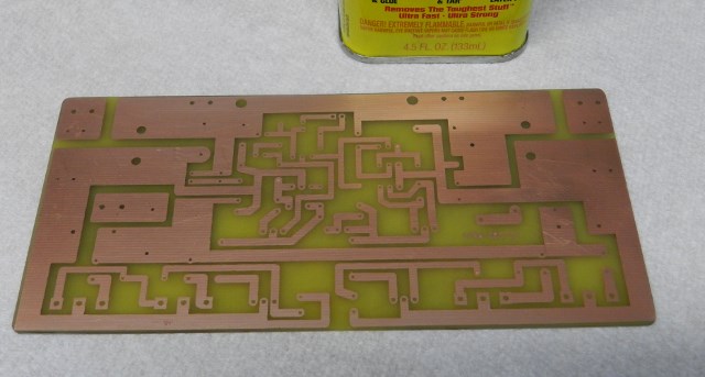
Now it is time to take the copper board to a ferric chloride solution bath. Carefully “READ THE INSTRUCTIONS” on the bottle before using this type of chemical or even before buying this product. It will take about 15 minutes or more depending on the temperature of the solution, to complete this process. Agitate the plastic container carefully without spilling. Observe the uncovered area of copper board is etched out slowly by the ferric chloride solution. When they are completely etched out, pour the ferric chloride solution into an empty plastic bottle using a plastic funnel. An empty plastic bottled water container works best for safe disposal purposes. Check with your local government authority for a waste disposal facility.
Remove copper resist by using either acetone, paint remover or by a product called "Goof Off", it works really good in removing the toner (I don’t work for Goof Off) and again “READ THE INSTRUCTIONS” on how to use these products.

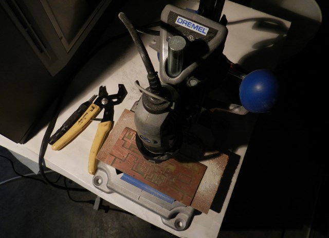
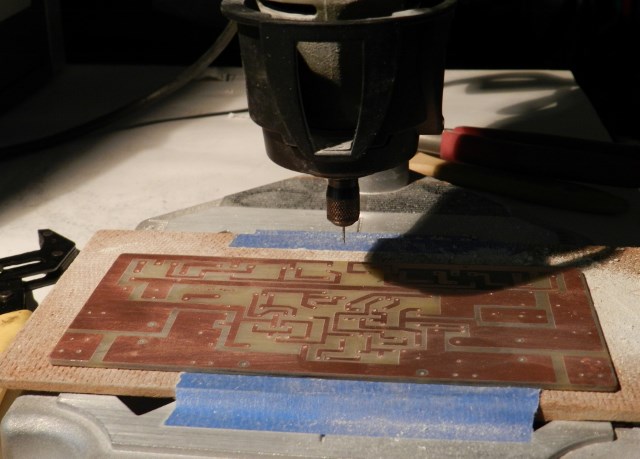
Now it is time to drill. I use a Dremel drill installed on a drill press stand, but you can use any mini drill that you may have. Several sizes of drill bits will be used, initially drill all holes with 0.027” (0.7mm) bit. For 1Amp diodes, T0220, T0126, 1/2W and 5W resistor, input header connector use 0.039” (1mm) bit. For fuse holders, output inductor, quik disconnect terminals and T03P output transistors use 0.05” (1.3mm) bit. For big filter capacitors use 0.07” (1.8mm) bit. For PCB mounting hole use 1/8” (3.2mm) bit.
Debur the copper board with fine sandpaper. Finally, it is ready to populate the board.