
Other Audio Related Projects
uPC1237 Speaker Protection and Power ON Delay Project
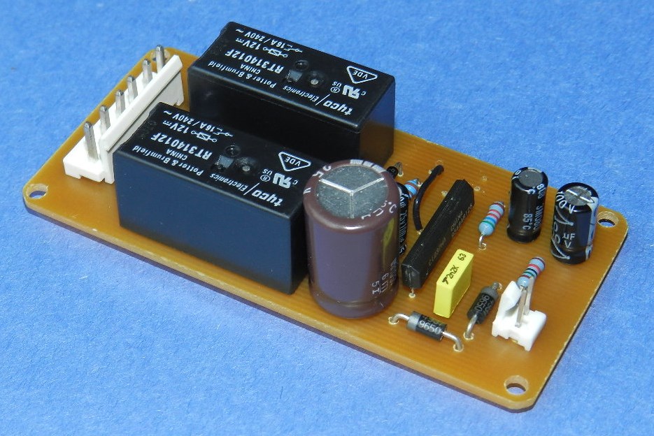
This project uses the uPC1237 an integrated circuit made by NEC; designed for protecting stereo power amplifiers and loudspeakers. It features AC power OFF detection, time delay to connect speakers to amplifier, and negative or positive output offset DC level detection. Please refer to upc1237 datasheet for more information.
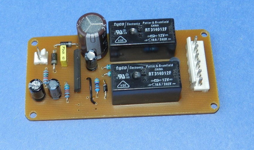
For this project I've decided to use 1 relay per channel. The coil current for 2 RT314012F is about 66mA, and the maximum current of the internal relay driver of uPC1237 at pin 6 is 80mA. The RC time constant for R2 and C2 is about 5 seconds. The reference voltage at pin 8 is 3.4V and the threshold level at pin 7 is 2.06V once these conditions are met the LED turns ON, indicating contact closure. The recommended value of the threshold resistors R5 and R6 connected at pin 2 is 56KΩ.
If you want to build this project, it is recommended to use a separate 12VAC transformer to power the circuit. The PCB layout and uPC1237 BOM are provided for free, as is, no warranty. Enjoy!

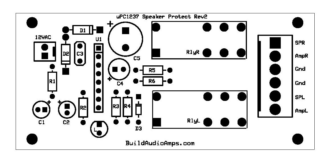
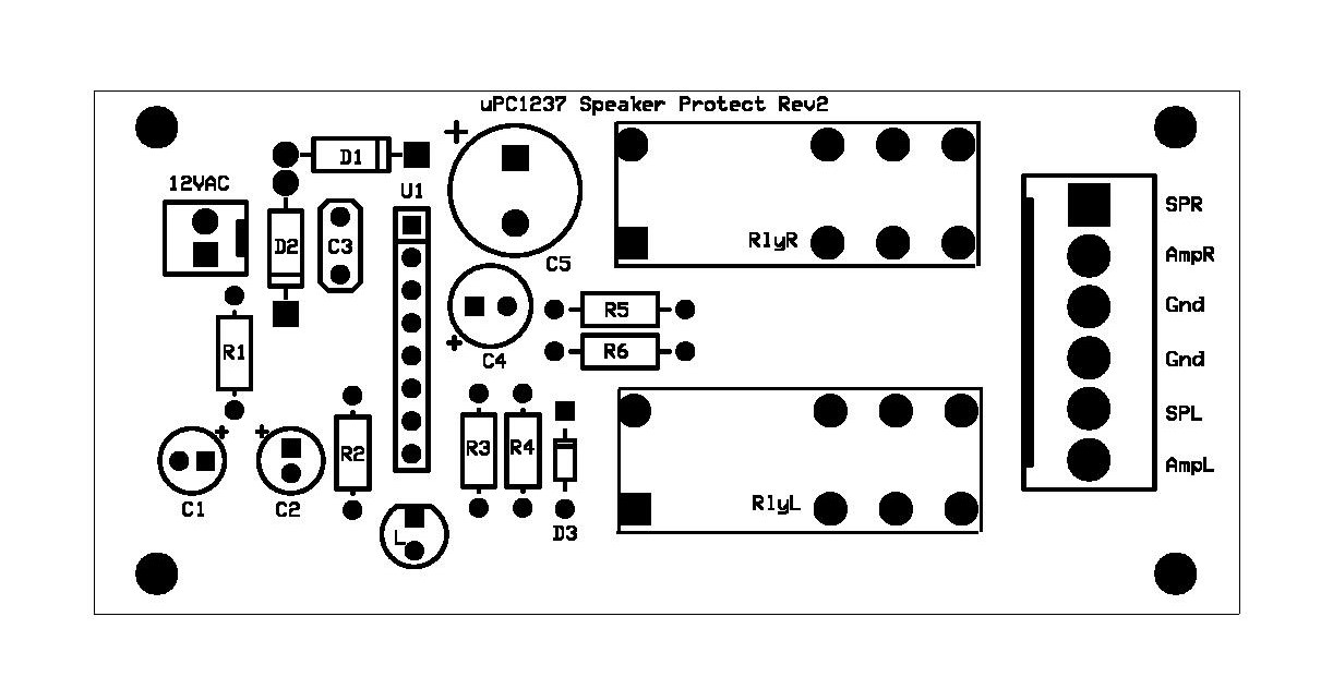
uPC1237 Silkscreen Parts Placement Layer
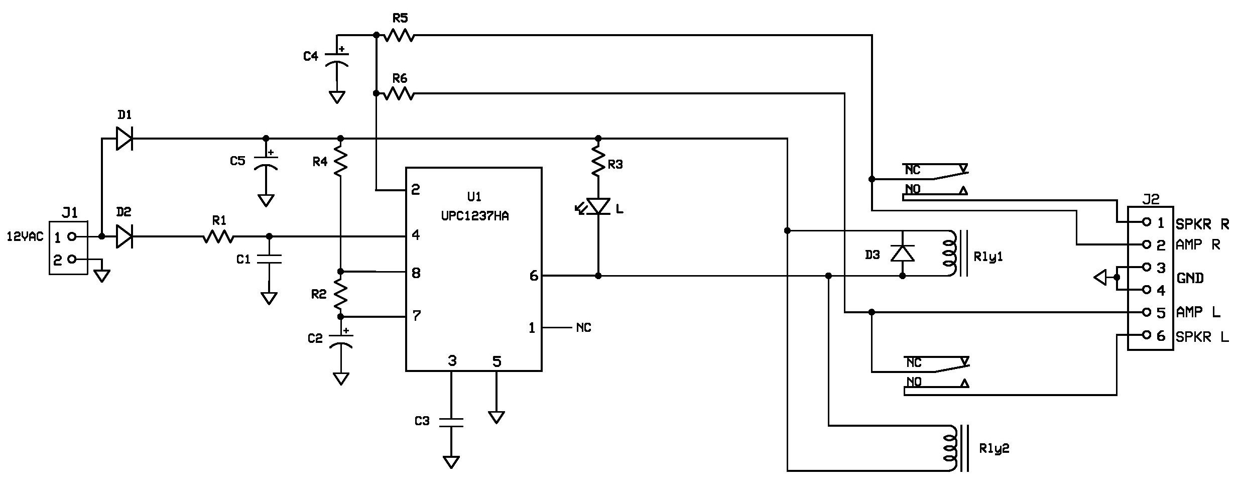
uPC1237 Schematic Diagram of Speaker Protection and Power ON Delay Project
Updated 12/6/2014
1. D3 should be 1N4148 or 1N914 missing in the BOM, it is 1N914 as populated in the prototype model.
2. Populate the LED in reverse of what is shown in the Silkscreen Parts Placement Layer of PCB. Thanks to Ivan L.
Updated 11/7/2016
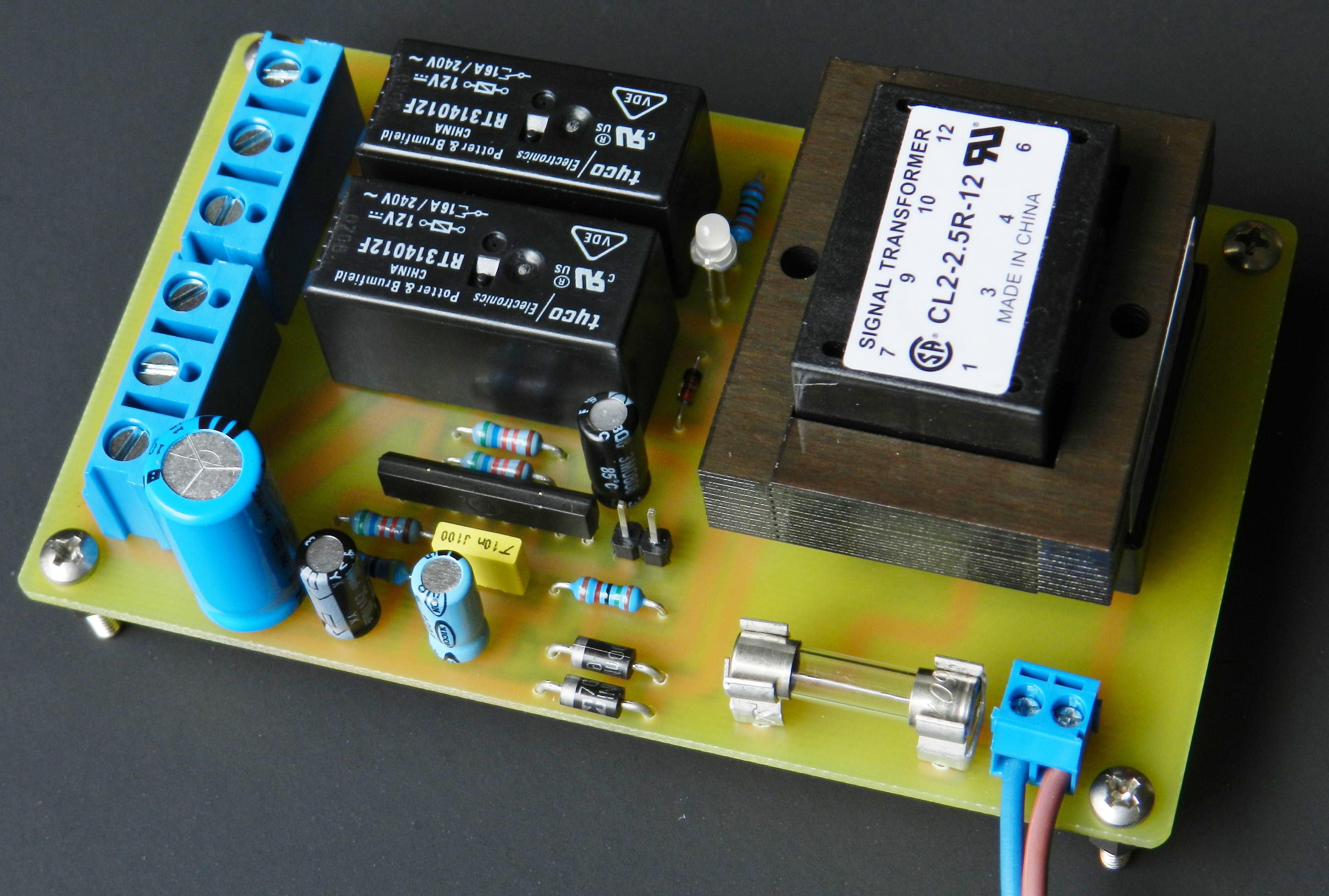

The uPC1237 project has been updated to include a fused PCB-mounted through-hole power transformer. The power transformer has an option to be wired for either 115VAC or 230VAC. The PCB layout has been completely revamped to make adjustments to the component footprints. The project module is now populated with easy accessible screw-type fixed terminal connectors for the AC input, speaker input and amplifier output terminations. The schematic diagram was completely redrawn for clarity and also shows the inclusion of the added parts in the BOM. If you’re interested with the updated project plans it’s available for free by request only to registered members.