PreAmp1
2-Channel Tone Control Circuit based on LME49720 Dual High Performance and High Fidelity Audio Operational Amplifier

Here's a brief description of LME49720 from Texas Instruments: The LME49720 is part of the ultra-low distortion, low noise and high slew rate operational amplifier series optimized and fully specified for high performance, high fidelity applications. Combining advanced leading-edge process technology with state-of-the-art circuit design, the LME49720 audio operational amplifiers deliver superior audio signal amplification for outstanding audio performance. The LME49720 combines extremely low voltage noise density with vanishing low THD+N (0.00003%) to easily satisfy the most demanding audio applications. Wow!
In my opinion, adding a tone control circuit into any audio system simply improves frequency response and provides more pleasing sound. In this project you can adjust the bass and treble frequencies simultaneously for both channels with the familiar cut-flat-boost positions of the controls.
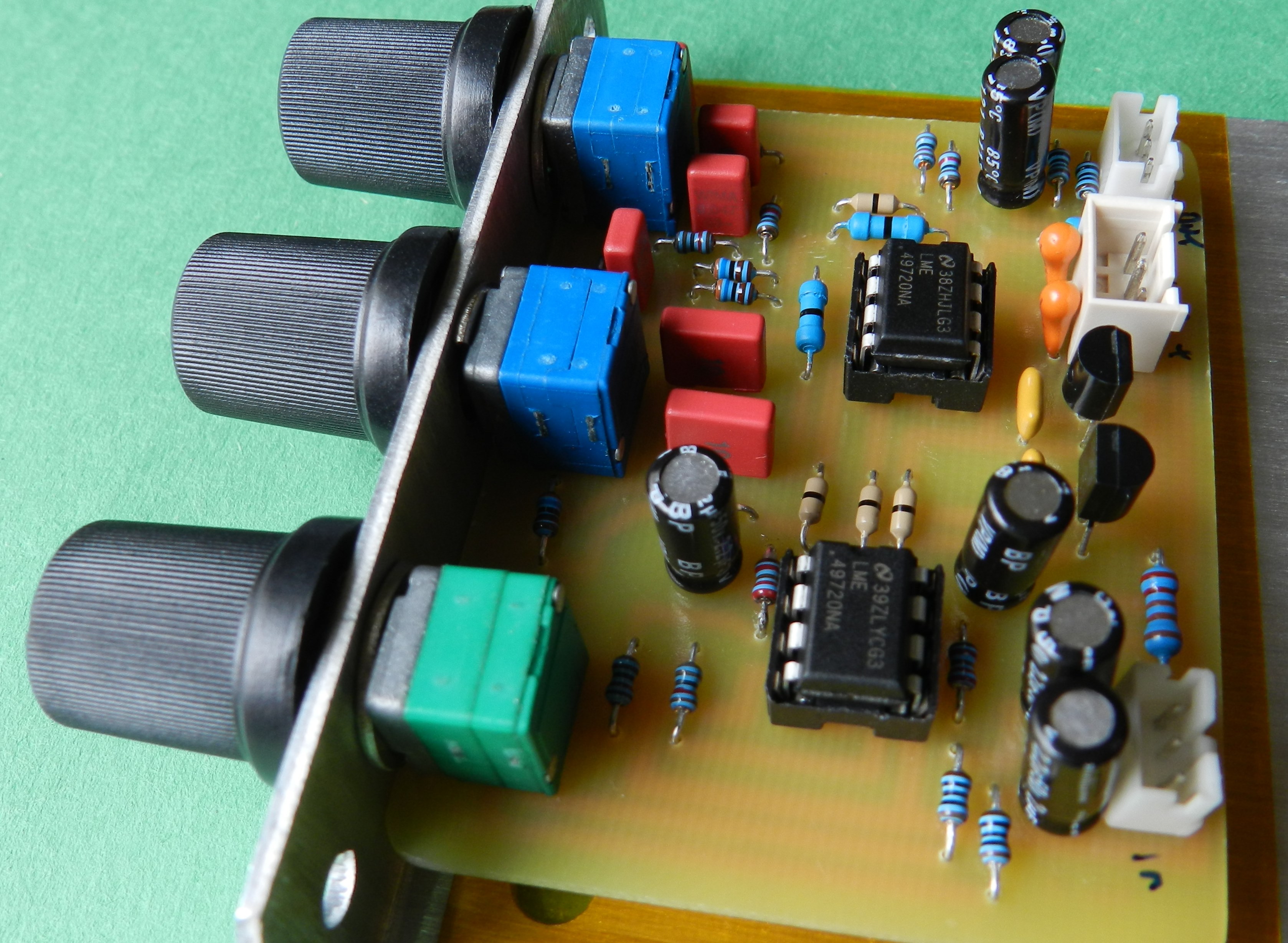
This project uses 2 LME49720 op amps for both channels. The schematic diagram is showing only one channel but the PCB layout was developed for 2 channels. The circuit consists of the first 1/2 op amp as an input buffer amplifier providing a gain of about 2 and isolation from any source impedance. The second 1/2 op amp is configured as an active filter amplifier whose feedback loop consists of passive components that adjusts the bass and treble frequency response.
The mid range frequencies are not affected by the tone controls. A flat frequency response can be obtained at mid positions of the bass and treble controls. VR1 is the volume control for adjusting the level of input signals simultaneously for both channels. VR2 is for low frequency while VR3 is for high frequency adjustments. You can add a balance control at the output, off the PCB, in my opinion this control is scarcely adjusted. For that reason, as well as space constraint on PCB and economy I did not include that feature. It’s up to you!
C1 and C7 at the input and output blocks any DC and in some ways set the minimum low frequency response of the tone control circuit. An onboard 3-pin positive and negative linear voltage regulators were added to power the LME49720. The maximum input voltage for this project is limited to +/-24VDC because of C8 and C9’s working voltage. A LED of SMT or TH package is populated at the bottom copper side of PCB and serves as a power ON indicator. If you want to build this project a PCB layout and LME49720 Tone Control BOM are provided for free, as is, no warranty. Enjoy!

LME49720 based Tone Control Schematic Diagram
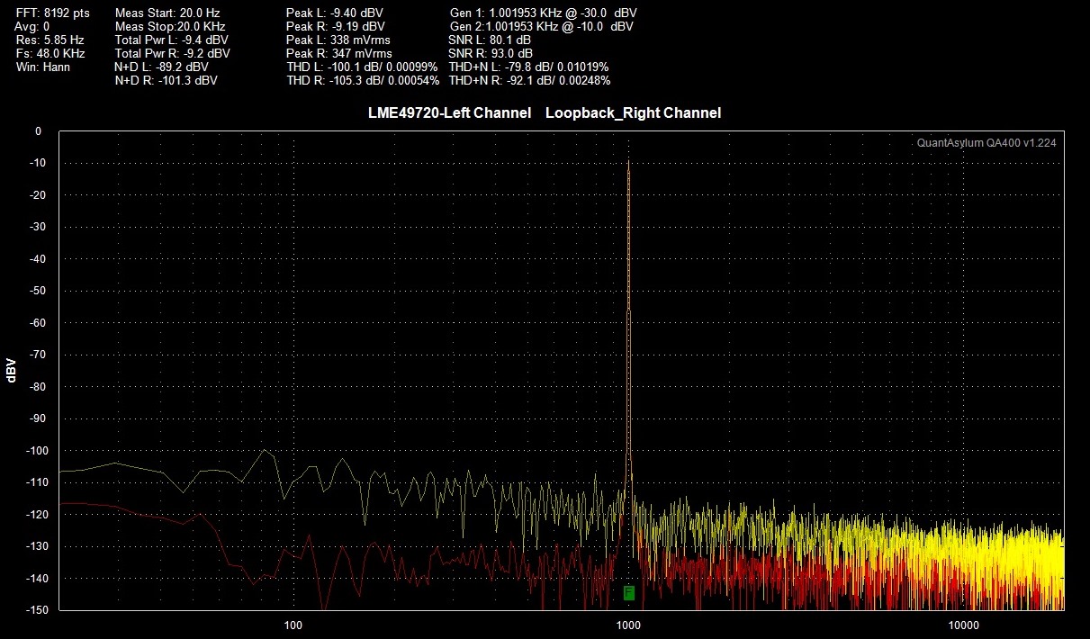
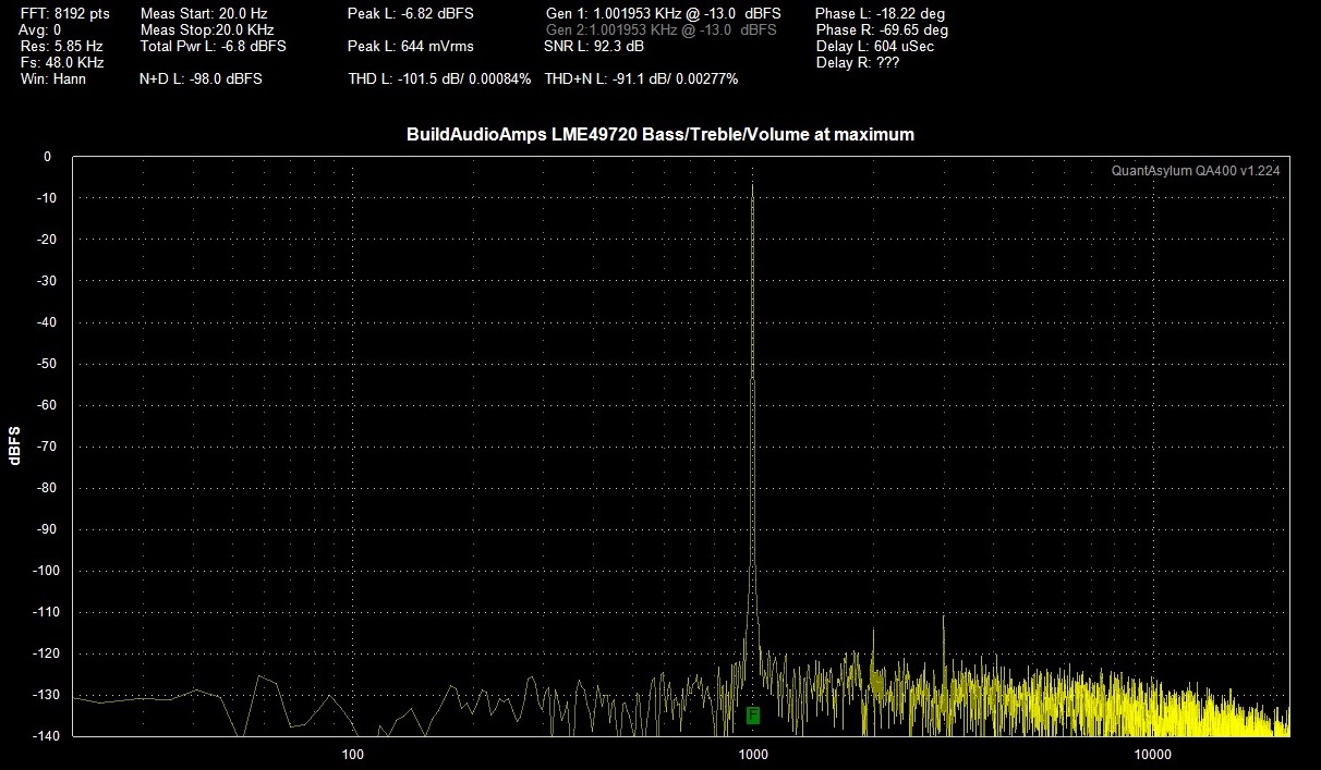 THD, THD+N and SNR test result using QA400 audio analyzer.
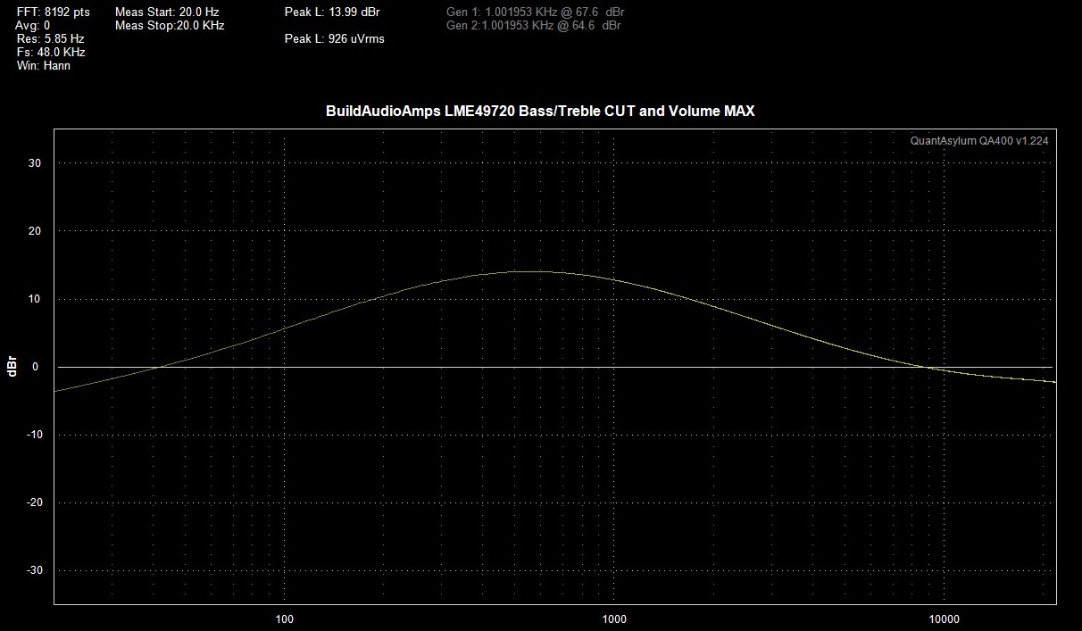 QA400 Frequency Response test result with Bass/Treble CUT and Volume at maximum.
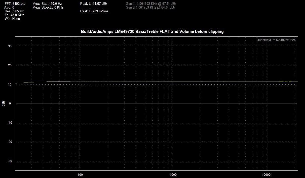 QA400 Frequency Response test result with Bass/Treble FLAT and Volume before clipping.
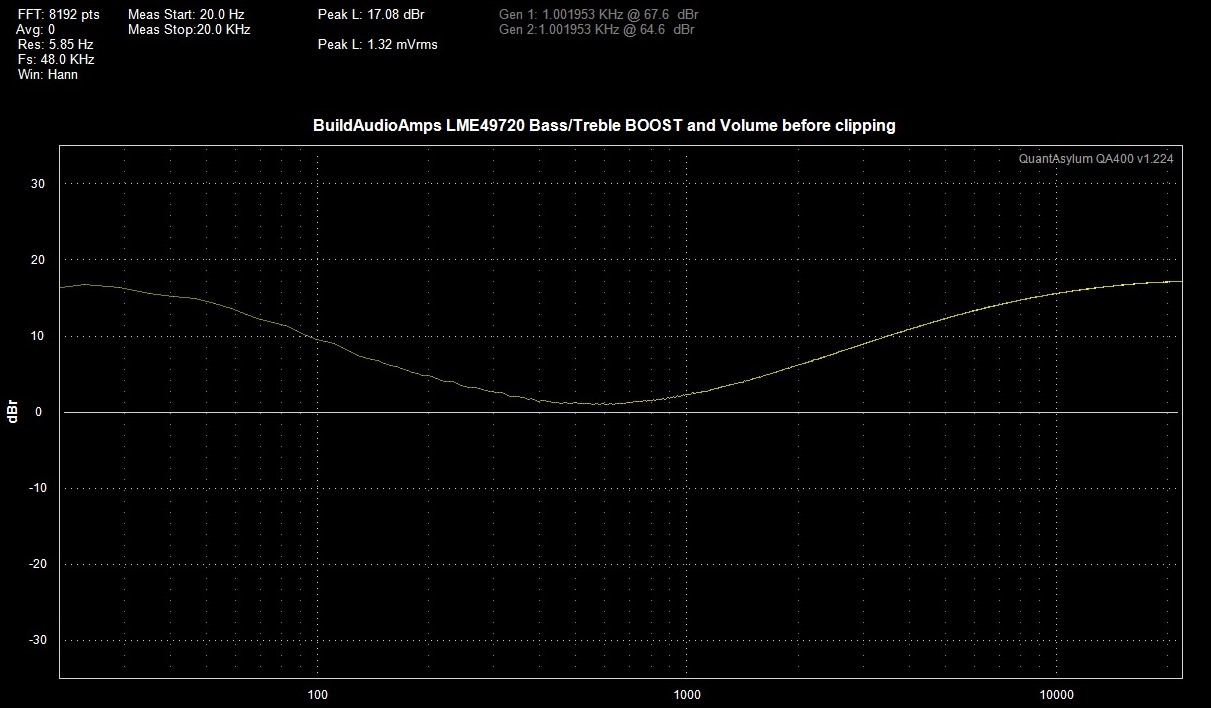 QA400 Frequency Response test result with Bass/Treble BOOST and Volume before clipping.


LME49720 Bottom Copper Layer LME49720 Silkscreen Parts Placement Layer