
PreAmp4
Another Tone Control Circuit
.jpg)
PreAmp4 is an 11-transistor two-stage tone control circuit. The first stage consists of Q1 thru Q7, configured with a paralleled 3-transistor circuit at the input and a quasi-complementary circuit at the output. The second stage consists of Q8 thru Q11, configured with a differential pair at the input and a full complementary circuit at the output.
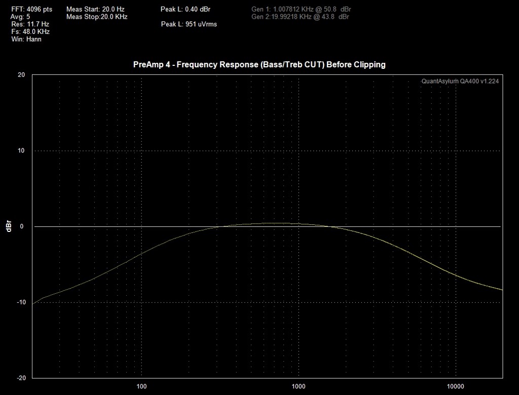
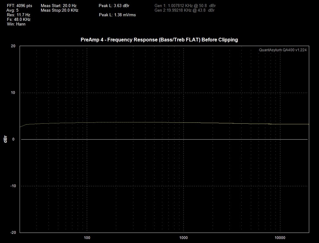
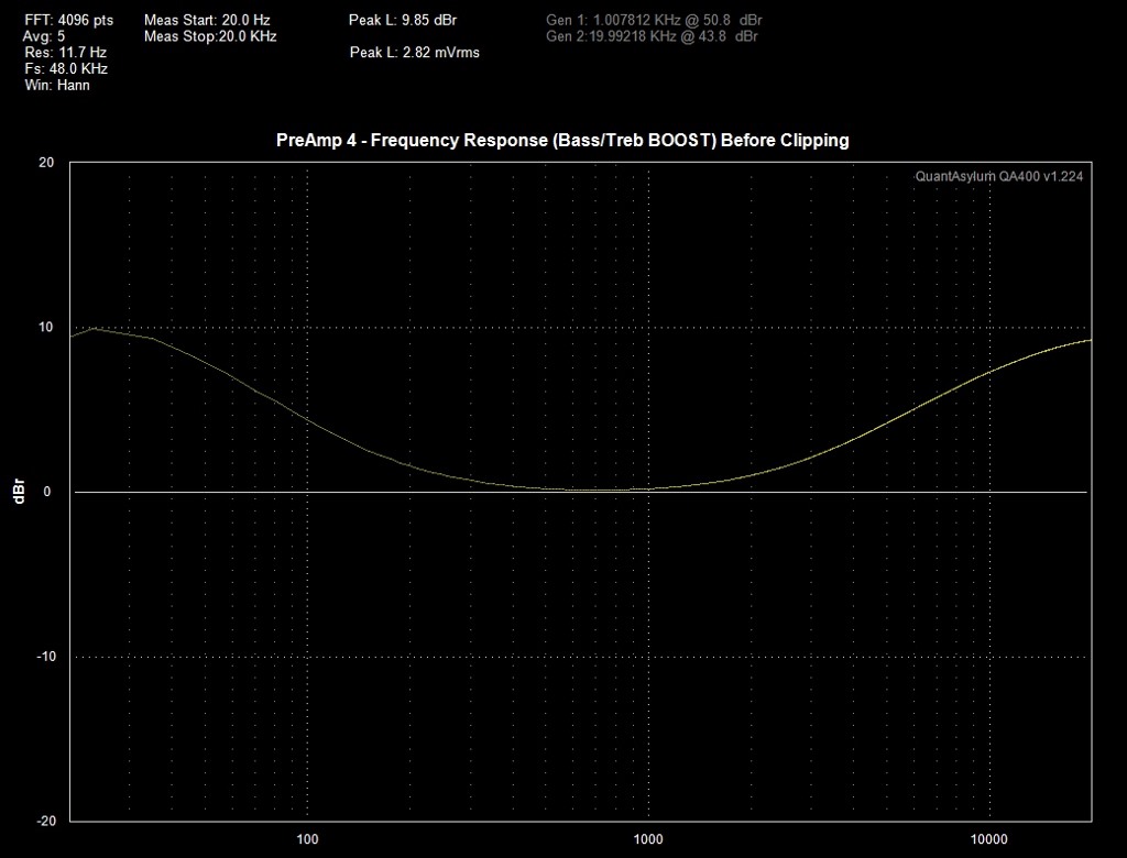
The gain of the first stage is determined by the ratio of R8 and R3 in series with C2. Passive components VR2, VR3, C8, C9, C10, R11, R12 and R13 act as active filters connected at the feedback loop of the second stage and controls the usual cut-flat-boost of the bass and treble frequencies.
Onboard 3-pin linear positive and negative voltage regulators were added in the PCB layout to power the tone control circuit. The maximum voltages at J3 are ±24VDC, because of the working voltage of C15 and C16. These capacitors may be changed with a higher working voltage up to 35VDC, the maximum input voltage of the linear regulators.
Not shown in the schematic diagram is the power ON indicator, consisting of a green LED in series with a current limiting resistor of SMD types. It’s an option to add these SMD components to the PCB! The provided PCB layout is for one channel; if you decide to use this project in a 2-channel stereo system, simply build 2 PCBs. The PCB layout, schematic diagram as well as the PreAmp4 BOM are provided for free by request, as is, no warranty.
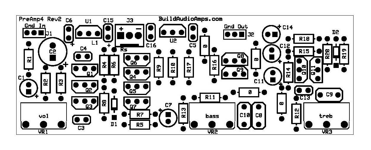 Top Silkscreen Parts Placement Layer of PCB.
The following "Tek hardcopy" waveform pictures are test results using an HP3312A function generator and a Tektronix TDS520D oscilloscope.
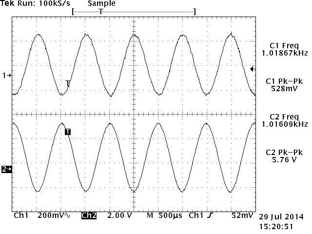
At 1KHz 500mVp-p sine wave input signal with volume, bass and treble controls adjusted at maximum setting.
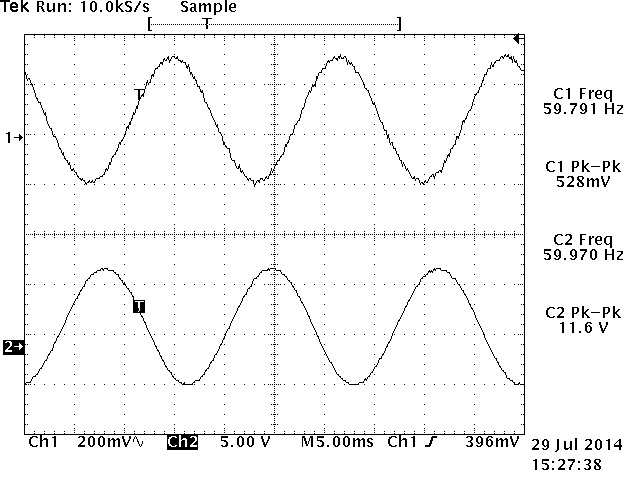
At 60Hz 500mVp-p sine wave input signal with volume, bass and treble controls adjusted at maximum setting.
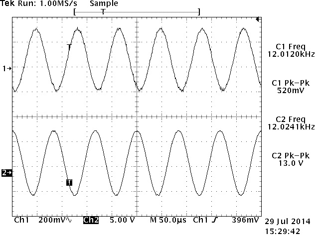
At 12KHz 500mVp-p sine wave input signal with volume, bass and treble controls adjusted at maximum setting.
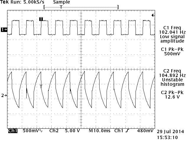
At 100Hz 500mVp-p square wave input signal, volume and bass controls adjusted at maximum with treble control at minimum setting.
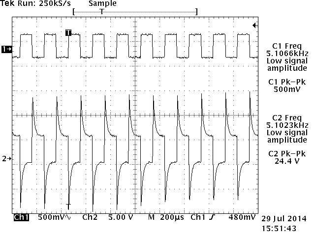
At 5KHz 500mVp-p square wave input signal with volume, bass and treble controls adjusted at maximum setting.
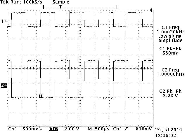
At 1KHz 500mVp-p square wave with bass/treble controls adjusted at mid/flat setting and volume control adjusted at maximum.
Updated 11/23/2016
.jpg)
 (2).jpg)