PreAmp5

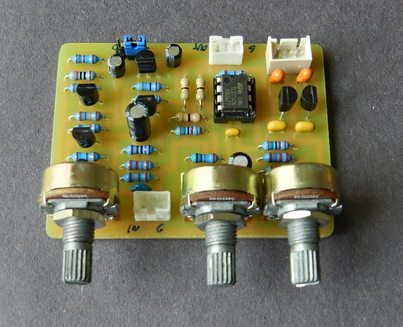
PreAmp5 project is another 2-stage tone control circuit that uses BJTs at the input and an op-amp at the output. The line level input stage consisting of Q1 thru Q4 provides a gain of about 18dB and is set by R7 and R9. The tone control stage is based on a non-inverting configuration of U1, that provides about ±7db of bass and treble frequencies. VR2, VR3, C5-C7, and R15-R18 connected in the feedback loop between the non-inverting input and output of U1 work as active filters that control the cut or boost of bass and treble frequencies. R12 and R14 connected at the ends of VR2 and VR3 limit the range of the cut or boost of the bass and treble signals. Reducing their resistance values increases the range of the cut or boost bass and treble signals.
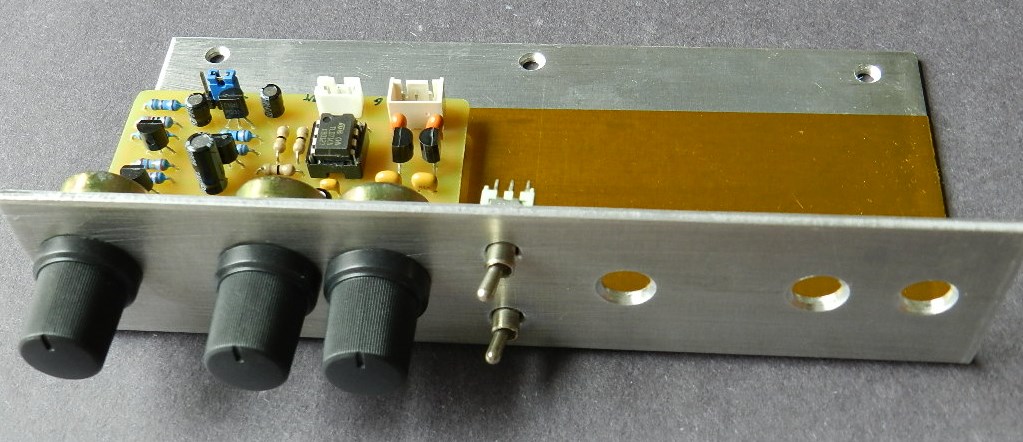
If you prefer, a switch may be inserted at J3 to function as a tone control bypass selector. An onboard TO-92 packaged positive and negative linear regulators were added in the PCB layout to power the tone control circuit. The maximum input voltage at J4 is limited to ±24VDC because of the working voltage of C10 and C11. If you decide to build this project for a two-channel stereo system, simply build another PCB. An almost completed example of a 2-channel PreAmp5 project is shown in the last picture.
Here’s something for the tinkerers, replace VR1 with a center-tapped potentiometer along with a few passive components to put together a loudness control circuit that boosts the low and high frequencies at a low volume setting. The loudness control, if properly built, makes the audio quality more pleasing to listen throughout the day!
The PCB layout and PreAmp5 BOM are provided for free, as is, no warranty.
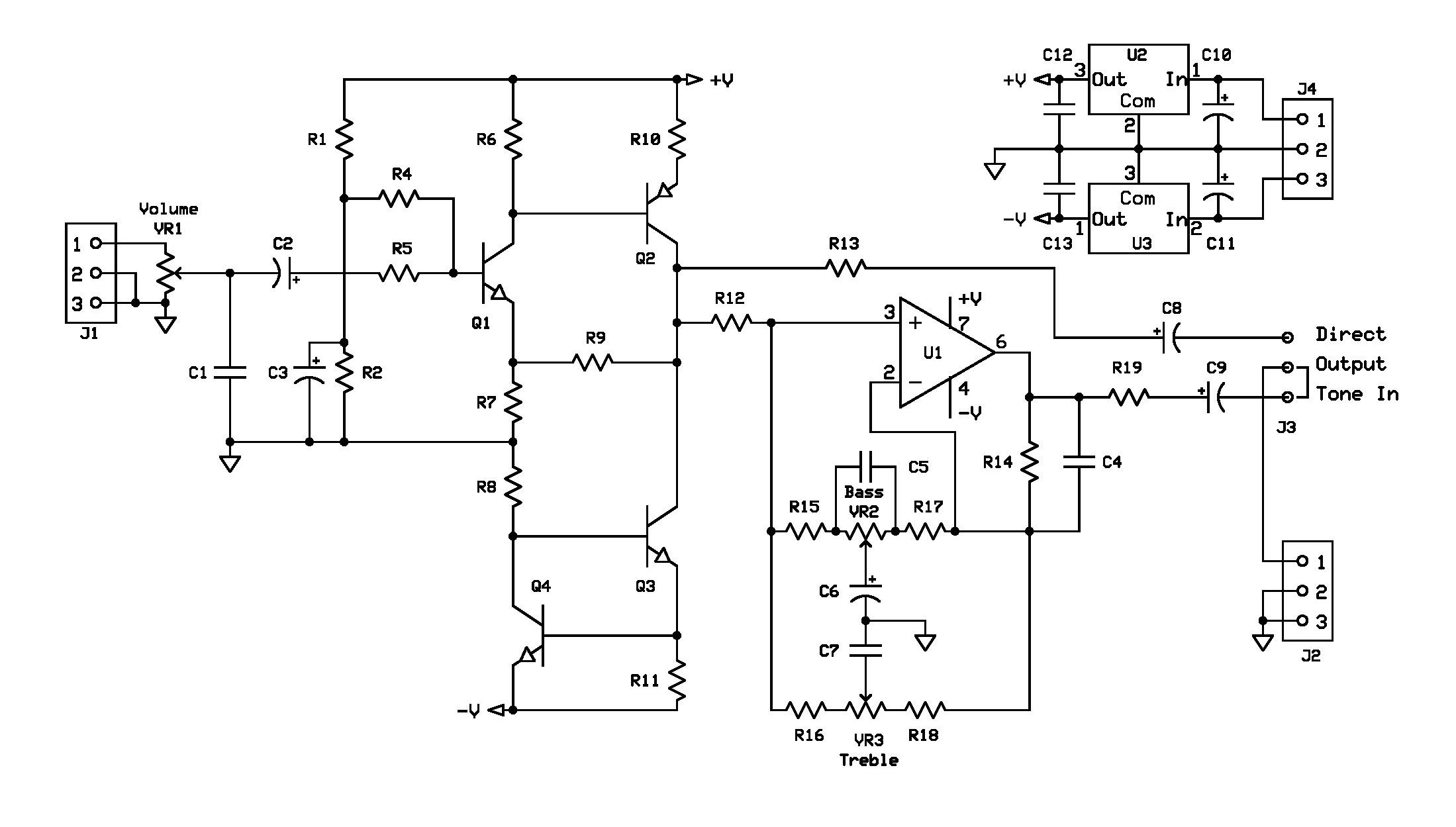 Schematic Diagram of PreAmp5 Project.
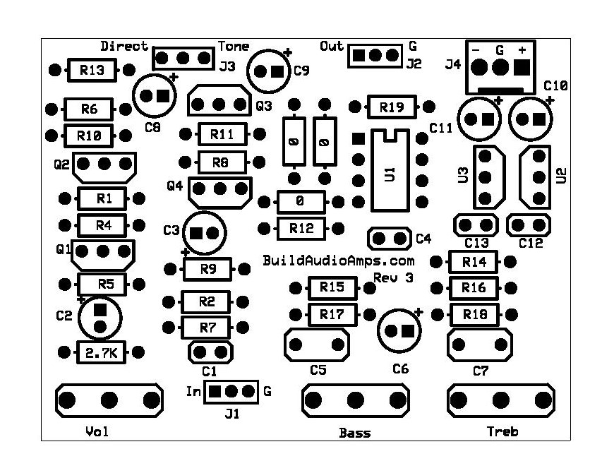
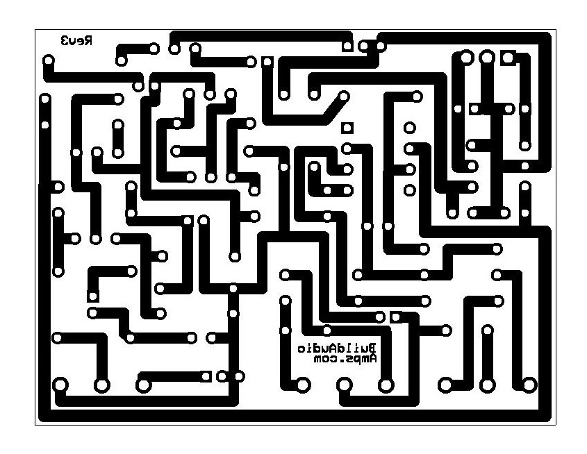
Silkscreen Parts Placement Layer of PCB. Bottom Copper Layer of PCB.