Project 56
Introduction. Project 56 is another implementation of International Rectifier’s IRS2092 Class D audio amplifier driver with PWM modulator and built-in protection. The measured power output of the prototype is about 160 watts into an 8Ω load with ±50VDC power supply rails. Project 56’s circuit is similar to a previous IRS2092 project, however, to improve its audio performance, a combination of series-pass and linear fixed voltage regulators were utilized to provide VAA and VSS power supplies, as well as the power supply requirement of the BiFET op-amp.
Another feature of this project is the inclusion of an over-voltage and under-voltage protection circuit. Project 56 is a half-bridge configuration, so bus-pumping phenomena might occur; that is caused by bi-directional energy flow. This allows the bus capacitors to be charged up from the load back to the supply. Horrible as it is, this condition never happened during the project’s listening test. But if it does occur, wherein the bus voltage increases above 68V or decreases below 39V, the protection circuit will be activated and will send a signal to the shutdown input pin 5 which disables the switching operation of the IRS2092.
One more feature of the project is the addition of a high performance BiFET inverting op-amp circuit that provides an inverse audio input signal for the IRS2092. This concept is useful when the project will be used in two-channel stereo systems, where one channel is operating in normal mode while the second channel is in inverse mode. This arrangement also eliminates supply bus pumping. There is a 3-pin connector populated in the PCB to select either normal or inverse mode. The speaker’s polarity on the inverse mode channel should be reversed (out of phase) to function properly.
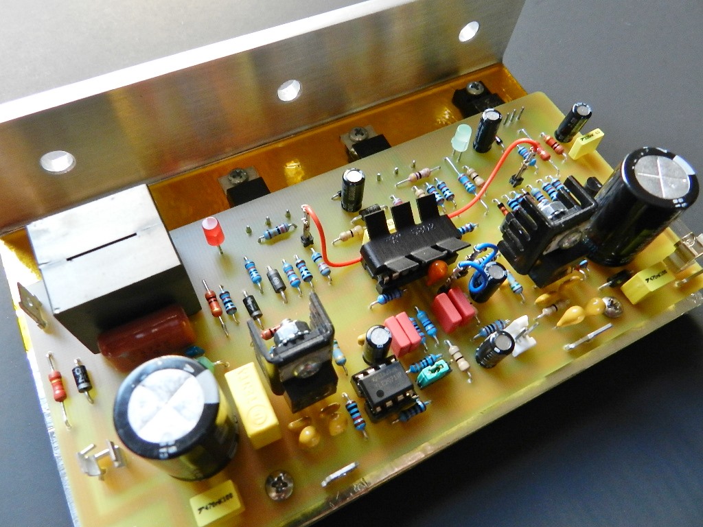
Building the project. Although there are additional populated components in this project, assembly is straightforward. The prototype uses 8 and 16 pins DIP IC sockets. It’s an option you might consider to ease the hassle of replacing these chips, if it ever becomes defective. When the project was in its developmental stage a few driver chips did fail and with the IC socket populated you simply remove and immediately install a new one. Furthermore, the op-amp in the input stage can easily be swapped with different types of your choice. The output inductor, L1, has a higher DC current rating than the one used in previous project.
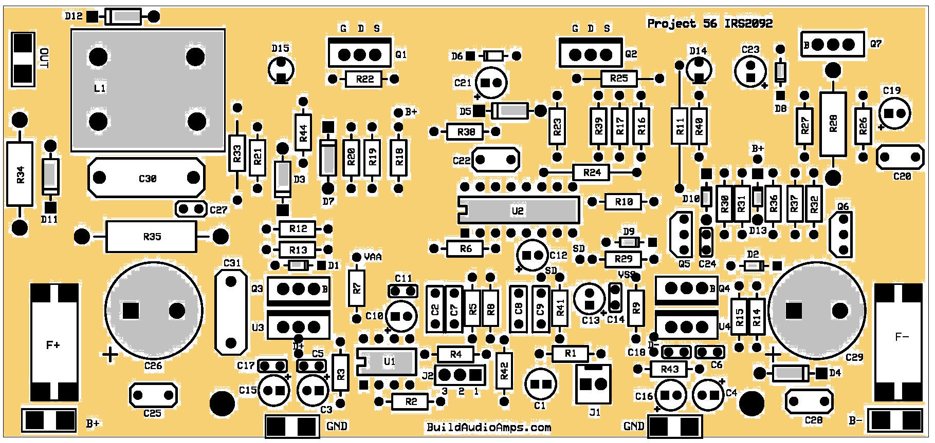
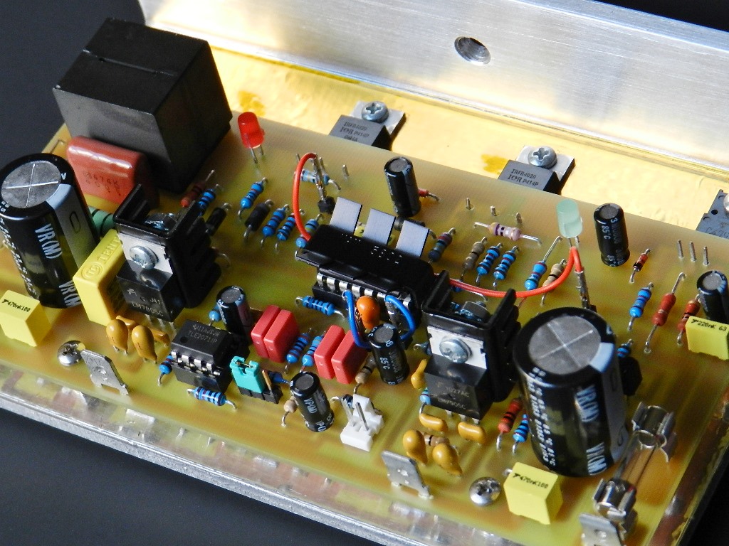
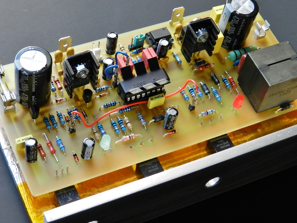
Project 56 Silkscreen Parts Placement Layer of PCB.
The prototype model was built on a 2.8” X 6.0” single-sided PCB. All through-hole components used in the prototype model are readily available standard parts. If you are interested in building this project and have read the Information and Policies section of this website, the schematic diagram, PCB layout and BOM (available only by request) are free, as is, no warranty.
Test procedure. Visually check the populated PCB for any assembly errors. Do not insert U1 and U2 into their sockets. The required power supply rails are obtained from a rectified and filtered 70VCT at 300VA power transformer. This should produce approximately ±50VDC rails (35V x 1.414). Be sure to measure the power supply output voltages first before connecting it into the amplifier under test.
With the power switched to ON, measure +5.6 volts (VAA voltage) at pin 1 of U2. This voltage should also be present at pin7 of U1. Next, measure –5.6 volts (VSS voltage) at pin 6 of U2 and pin4 of U1 with respect to ground. Then, measure the Vcc at the emitter of Q7; this should read about 15VDC also accessible at pin 12 of U2’s IC socket. If these housekeeping voltages are verified, switch off the power supply and allow the voltages to drain completely to 0V before inserting U1 and U2 into their respective IC sockets.
After installing all the necessary interconnecting wires to the amplifier under test, switch the power supply to ON. The red LED should turn on immediately while the green LED should be off after a brief moment. In some conditions the green LED does not turn on, it’s just waiting for an audio input signal at J1. Another condition is a blinking green LED. This is an indication of a very high self-oscillating switching frequency and you need to decrease the value of R8. Here’s AN-1138 to help you understand the functional description of the IRS2092.
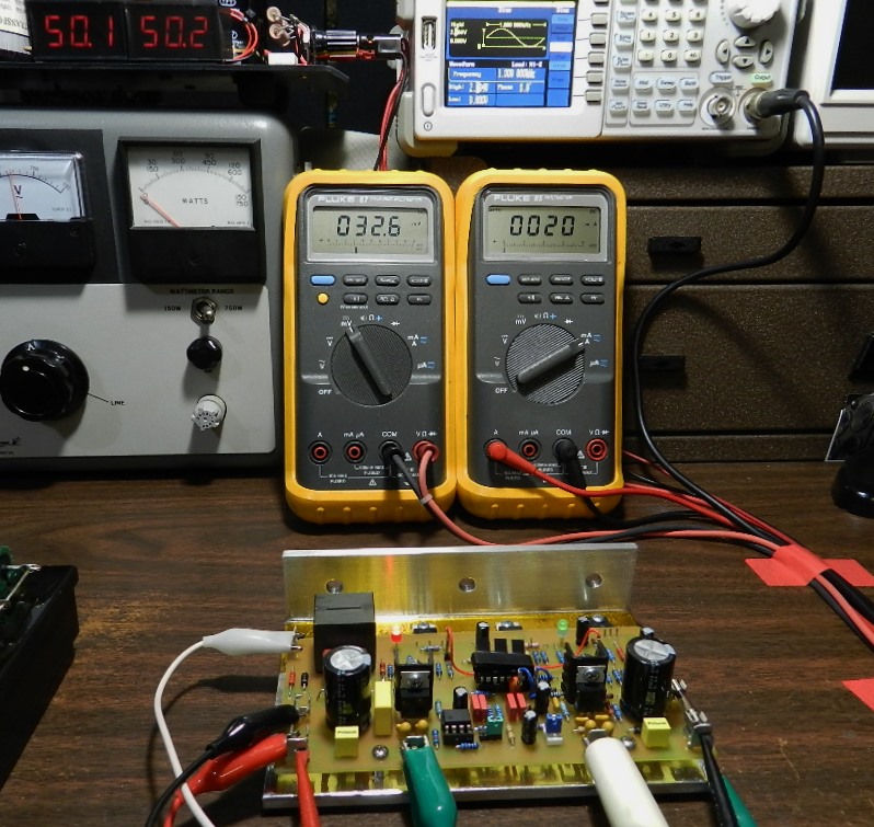
The picture above is showing the initial test measurements of the project’s prototype. The DMM on the left is measuring the DC offset voltage of the amplifier at 32.6mV. The DMM is connected across the output of the amplifier (white and green test clips). This DC voltage could be anywhere from a few millivolts to 50mV. The DMM on the right is measuring the total current of the amplifier at 20mA. This DMM is connected across the B+ fuse terminals (red and black test clips). This current should not exceed more than 60mA, otherwise there is something wrong with your project.
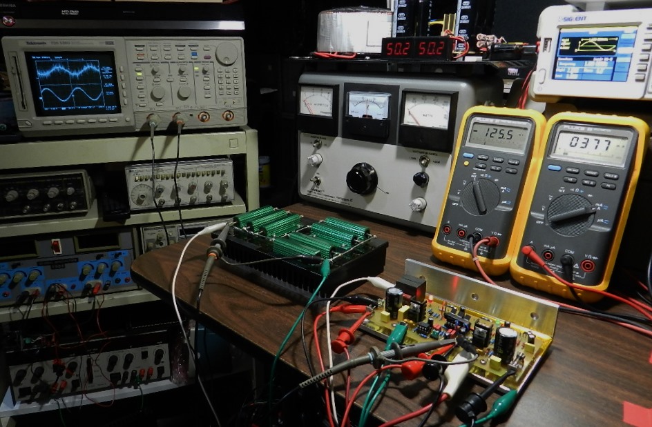
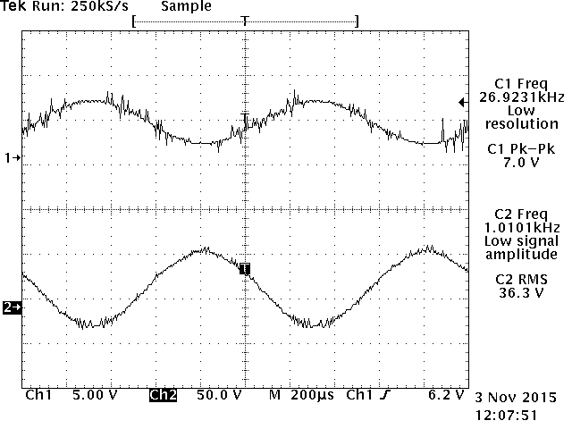
The picture on the left above shows the power output measurement using a signal generator, oscilloscope and 8Ω dummy load. The signal generator was adjusted to provide an output of 1KHz sine wave and connected directly to J1. An 8Ω dummy load is connected at the output of the amplifier under test. Channel 1 probe of the oscilloscope is connected at J1 while channel 2 probe is connected across the dummy load. The voltage across the 8Ω load measures 36.3Vrms before clipping with an input voltage of 7Vp-p, as shown on the right side picture above. This corresponds to a power output of about 164 watts.
The self-oscillating frequency is measured at pin 4 of U2 shown on the left picture below. The gate output signals at LO pin 11 and HO pin14 was also verified and shown in the following pictures in the middle and on the right respectively.
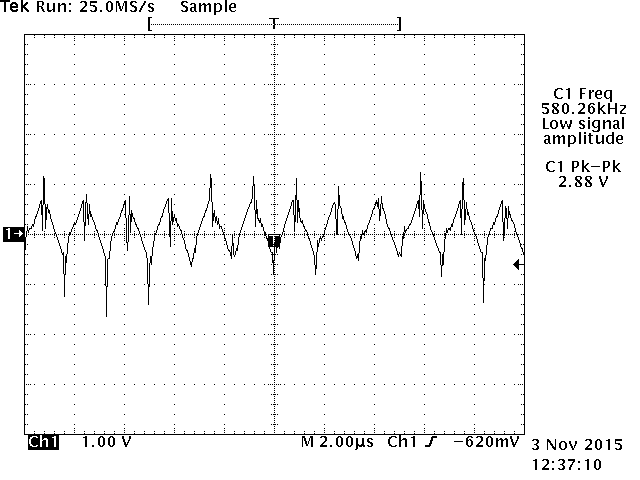
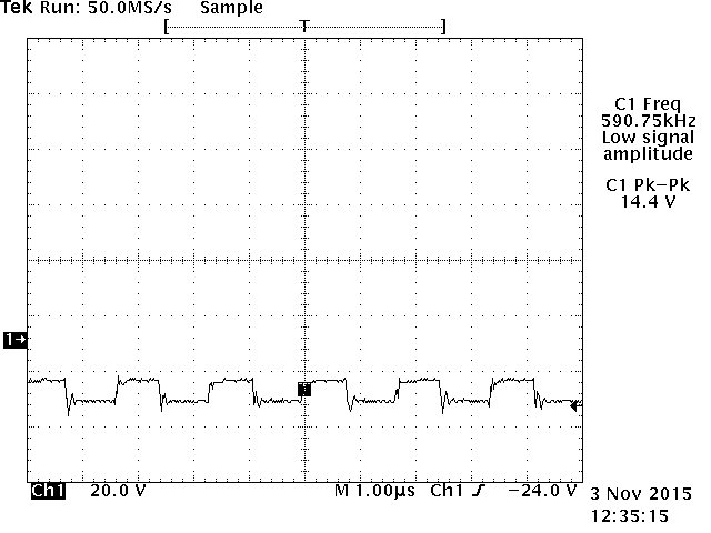
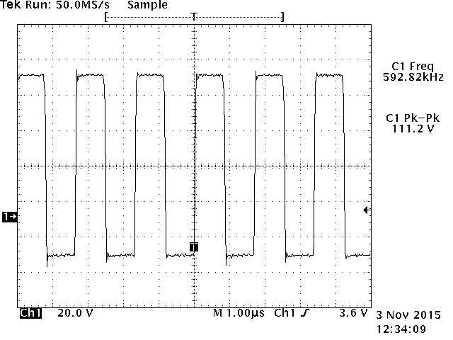
Waveform signal at COMP pin4 Waveform signal at LO pin11 Waveform signal at HO pin14

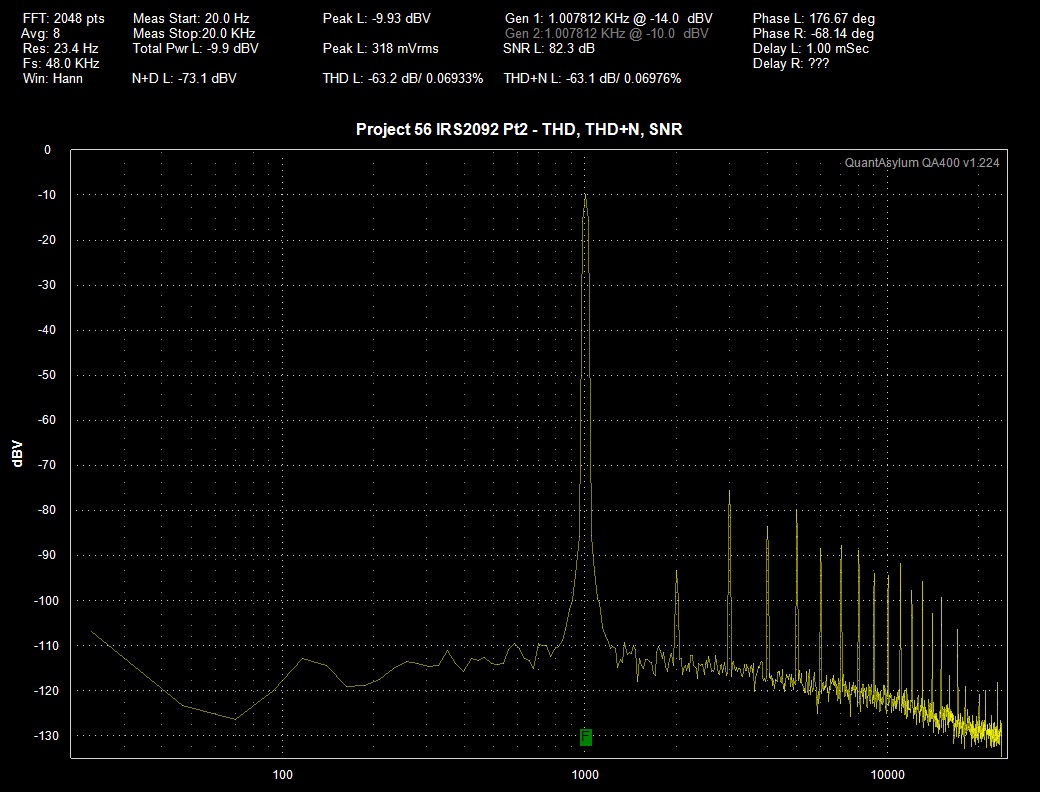
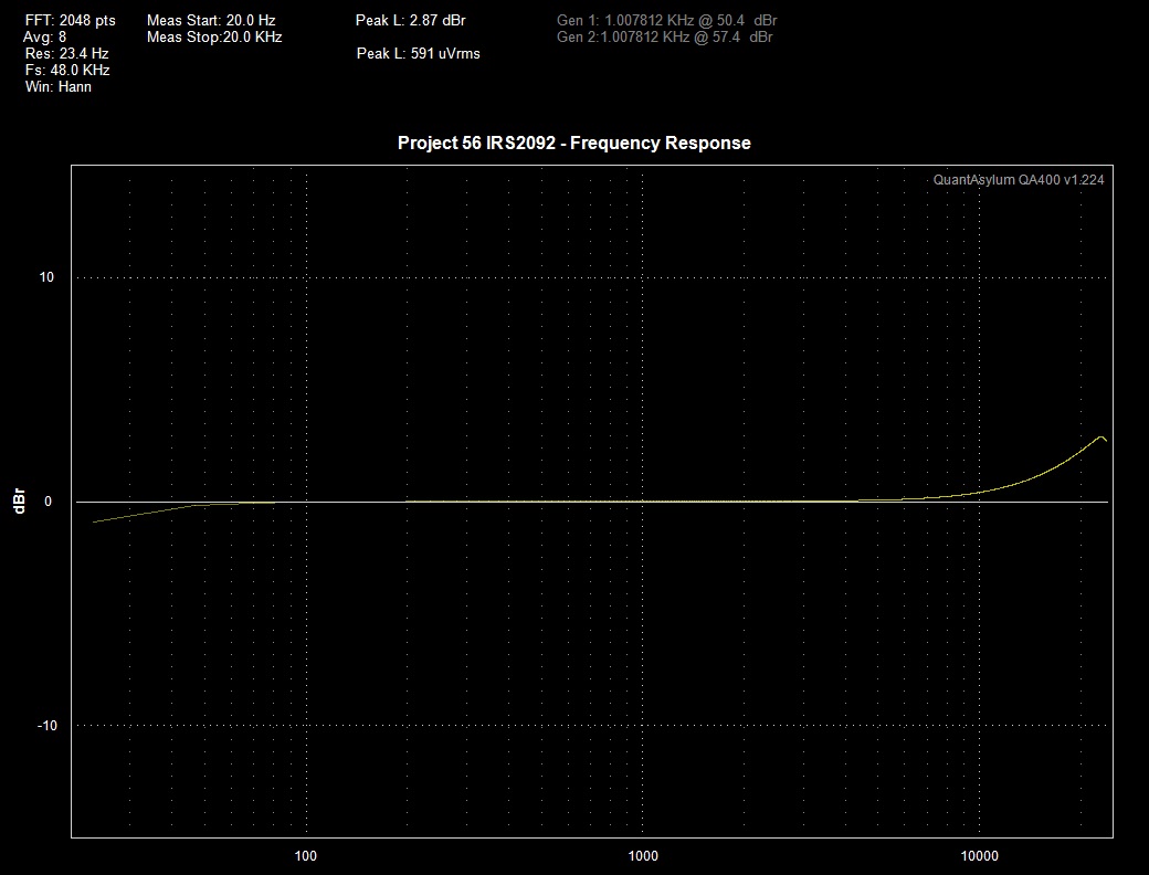
QA 400 audio analyzer tests. A QuantAsylum QA400 USB audio analyzer and QA190 low-noise differential probe were utilized to measure noise, distortion, SNR and the frequency response of the prototype. The basic test setup is shown in the picture above and its test results shown below.
How does it sound? After looking at the test results, it was not expected that the prototype would perform very well in listening test, but it did not disappoint! This proved that what we hear does not always agree with what was measured. The prototype was mated with a modified LME49720 PreAmp1 project, a Toshiba HD-A2 player and several test speakers. Playing different music genre from several CD albums the audio quality reproduced was pleasant and impressive. It’s safe to say that the sonic quality it reproduced was as accurate and dynamic as it could get.