Project 55
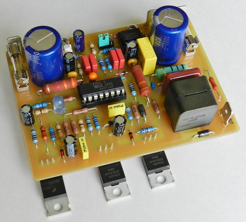
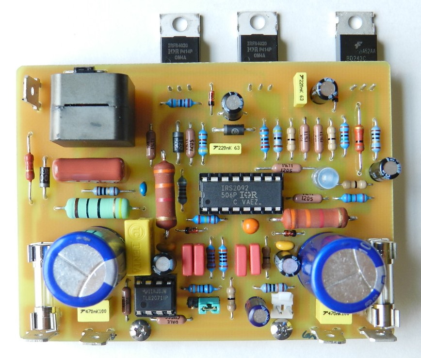
Introduction. Project 55 was inspired by International Rectifier’s reference design of IRAUDAMP7D, a two-channel scalable Class D power amplifier module. The project is a single-ended Class D audio power amplifier with an IRS2092 chip. The IRS2092 is a high-voltage, high-speed MOSFET PWM generator, gate driver with internal dead-time and protection functions specifically designed for Class D audio power amplifier applications. The built-in protection includes over-current (OCP), under-voltage (UVP) and bi-directional current protection for both the high-side and low-side MOSFETs. A click and pop elimination function is also included that prevents audible transient noise.
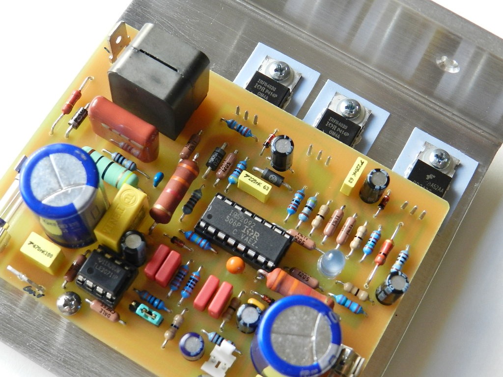
The IRS2092 is a popular Class D audio amplifier driver chip that is available either in SOIC16N (IRS2092SPBF) or PDIP16 (IRS2092PBF) packages. The IRS2092SPBF is surface mounted while IRS2092PBF is through-hole; both have 16 pins and the same lead assignments. However, for this project a socketed PDIP-16 version was chosen for ease in replacement and assembly.
Project 55’s prototype was developed for only one channel, but when combined with a second channel, you have the option to decide on either normal or inversed signal to the input of the IRS2092. Adding a low-noise inverting op-amp circuit in front of the IRS2092 produces the inversed signal. This is useful in eliminating bus-pumping effect in half-bridge 2-channel (stereo) systems. The op-amp circuit can also be modified as a pre-amp to provide a more dynamic high quality audio output.
The DCP, OTP, UVP and OVP external protection circuitry in the IRAUDAMP7D design were intentionally excluded for simplicity and economics. An optional OVP and UVP circuit is included in the schematic diagram of Project 55. The over-voltage protection zener diode conducts when it reaches an overvoltage condition, while the under-voltage protection diode stops conducting when an undervoltage condition is attained. When these conditions occur, the second 2N3904 transistor then sends a signal to U2_CSD pin 5 through a 1N4148 diode in series with a 100-ohm resistor and shuts off D9. You may also use the uPC1237 project for speaker protection and peace of mind.
The prototype produces more than 140 watts of power output into an 8-ohm load with ±50VDC power supply rails, as measured and shown in Figures 1 and 2. It requires only two external TO-220 packaged power MOSFETs to efficiently attain the desired power output with less heat. No component populated in the PCB goes higher than 60°C, except for the 2W resistors, R8 and R13; please refer to the schematic diagram from hereon. The BOM and PCB layout are available by request only.
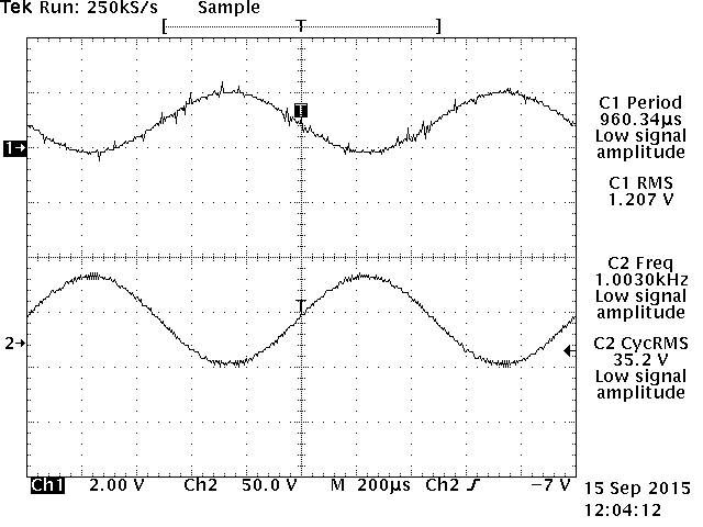
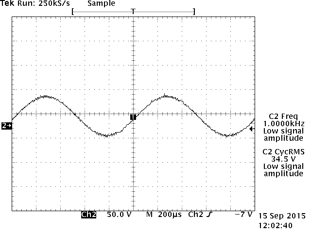
Figure 1. 1KHz input and output signal waveforms. Figure 2. 1KHz output signal waveform after LPF.
Brief description of the circuit. The audio frequency input signal is applied at J1 through a DC blocking bi-polar capacitor, C1. The input impedance of the amplifier is equal to R1. A 3-position 0.100” pitch (2.54mm) pin jumper connector, J2, allows the user to select either normal or inverted signal into the inverting input of U2. Pin 2 of J2 is connected to a low-pass filter, R4-C2, to prevent RF signals from entering the amplifier. The low-pass filter also reduces the amplitude of the difficult-to-eliminate (shown in Figure 1) high-frequency switching artefact of the output from entering the input of U2 because of feedback resistor, R6 and input resistor, R5. The voltage gain of the amplifier is 36.04 or 31dB, determined by R6/R4+R5. Changing their values will also alter the voltage gain of the amplifier, if so desired. To change the voltage gain, change the input resistor R5. Changing R6 may affect PWM control loop and will result to poor audio performance.
The amplifier requires ±50VDC, applied at the B± lug terminals through F± fuses. These are then filtered and decoupled by C14 through C17. The drain of Q2 is connected to the B+ rail and the source of Q3 and pin 10 of U2 are connected to the B- rail. The required ±5.6VDC @ 10mA for analog signal processing, VAA and VSS, are also taken from these rails through R13, D2 and R8, D1. The Vcc supply of U2 at pin 12 is derived from the negative supply rail through D4, Q1 and R22. The gate driver section of IRS2092 uses Vcc to drive the gates of the power MOSFETs. The Vcc is referenced to the negative power supply rail. Zener diode, D3 and C20 forms a bootstrap floating supply for the HO gate driver at pin 14. The Vcc also internally powers the LO gate driver at pin 11. The output waveforms of LO and HO pin are shown in Figure 3 and 4 respectively.
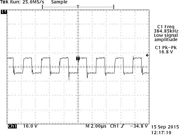
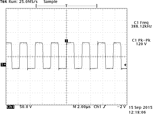
Figure 3. Output at pin 11 of IRS2092. Figure 4. Output at pin 14 of IRS2092.
Integration resistor, R7, and integration capacitors, C3 and C4, connected at pin 4 of U2 determines the measured self-oscillating frequency at 387.349KHz with amplitude of 2.08Vp-p, see Figure 5. IR recommends 400KHz ±25KHz as the ideal self-oscillating frequency for typical designs. This frequency can be achieved by tweaking the value of R7.
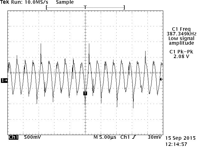
Figure 5. Self-oscillating frequency output at pin 4 of IRS2092.
The output of the amplifier goes through a low-pass filter consisting of L1 and C18. This low-pass filter extracts the switching carrier signal while leaving only the desired audio frequency signals for the speaker load. The LPF inductor, L1, was specially chosen for linearity and minimizes distortion at higher frequency. Two snubber or Zobel networks are connected at the output, R25-C13 and R27-C19, to prevent oscillation and improve overall stability of the amplifier. D7 and D8 clamps any output beyond B+ and B- mainly caused by loudspeaker excursions or speaker coil inductance.
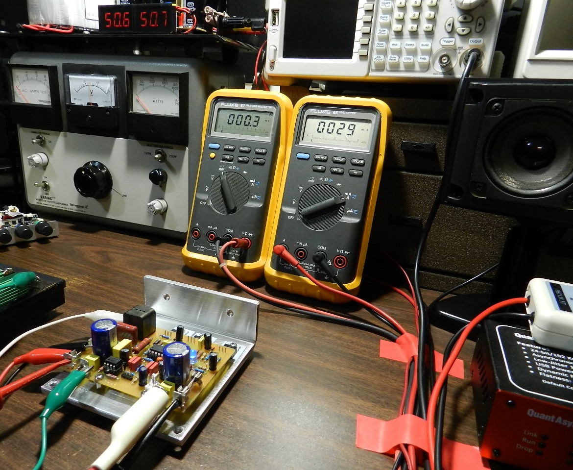
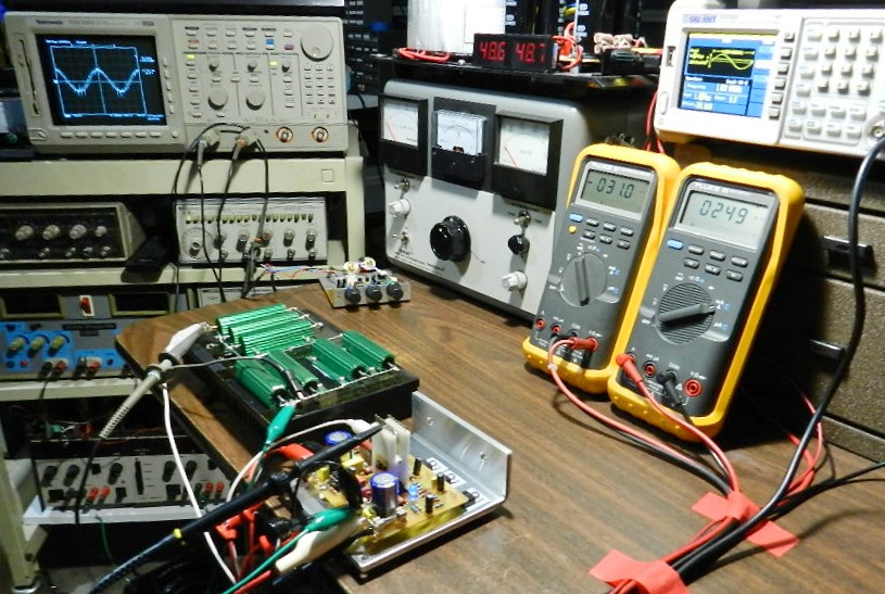
Figure 6. Initial test setup of Project 55 Figure 7. Power output measurement test setup of Project 55
Test Procedures. Visually check the populated PCB for any assembly errors. Do not insert U1 and U2 into their sockets. The required power supply rails are obtained from a rectified and filtered 70VCT at 300VA power transformer. This should produce approximately ±50VDC rails (35V x 1.414). Be sure to measure the power supply output voltages first before connecting to the amplifier under test. With the power switched to OFF, connect the power supply output to the amplifier under test. With the power switched to ON, measure the voltage across D1 and D2. It should read about +5.6VDC at pin 1 of U2 and –5.6VDC at pin 6 of U2 with respect to ground. Measure the voltage at the emitter of Q1; this should read about 15VDC also available at pin 12 of U2’s socket. If these voltages are verified, switch off the power supply and allow the voltages to drain completely to 0V before inserting U1 and U2 into their sockets.
Remove the F+ fuse, if installed, and replace it with a DMM set at mA or A range. This will measure the quiescent or idling current of the amplifier under test. This reading should be less than 50mA with no input signal. Connect another DMM set to mV range across the output and ground of the amplifier lug terminals. This will measure the DC offset voltage output of the amplifier under test. This reading should be near 0mV to about 50mV with no input signal and no jumper installed at J2.
After installing all the necessary interconnecting wires to the amplifier under test, switch the power supply to ON. The blue LED should lit up after a brief moment. Under normal condition you should obtain the same DMM readings as shown in Figure 6. If not, switch OFF the power supply immediately and check for assembly errors. The initial test results of the prototype are shown in Figure 6. The DMM on the left is measuring the DC offset voltage at 0.3mV with no input signal and no jumper installed at J2. The DMM on the right is measuring the idling current at 29mA with the same conditions mentioned.
Figure 7 shows the power output measurement using a signal generator, oscilloscope and 8-ohm dummy load. The signal generator was adjusted to provide an output of 1KHz sine wave at 1.2Vrms and connected directly to J1. An 8-ohm dummy load is connected at the output of the amplifier under test. Channel 1 probe of the oscilloscope is connected at J1 while channel 2 probe is connected across the dummy load. The voltage across the 8-ohm load measures 35.2Vrms before clipping with an input voltage of 1.207Vrms, as shown in Figure 1. This corresponds to a power output of 154.88 watts.
The self-oscillating frequency is measured at pin 4 of U2 and shown in Figure 5. The gate output signals at LO pin 11 and HO pin14 were verified and shown in Figures 3 and 4 respectively.
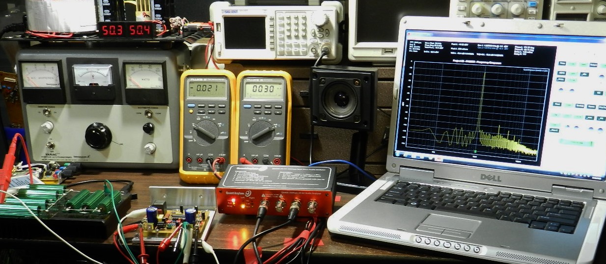
Figure 8. Noise, THD, THD+N, SNR and Frequency Response test setup of Project 55 with QA400
QA 400 audio analyzer tests. A QuantAsylum’s QA400 USB audio analyzer and QA190 low-noise differential probe were utilized to measure noise, distortion, SNR and the frequency response of the prototype. Figure 8 shows the basic test setup while Figures 9 and 10 shows the test results.
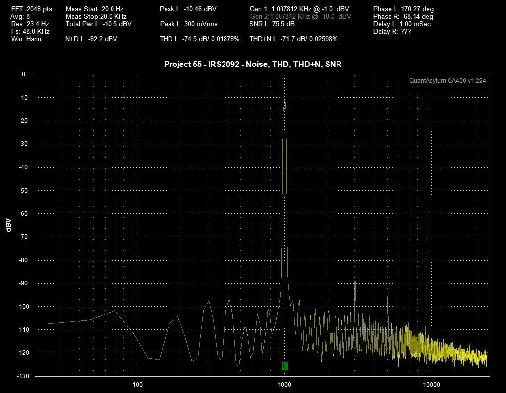
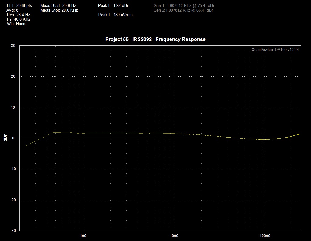
Figure 9. Project 55 QA400 Audio Analyzer test result Figure 10. Project 55 Frequency Response test result
How does it sound? After looking at the test results, it was not expected that the prototype would perform very well in the listening test, but surprisingly it did! This proved the “what we hear does not always agree with what was being measured” theory to be significantly correct. The prototype was mated with a modified LME49720 PreAmp1 project, a Toshiba HD-A2 player and several paralleled test speakers. Playing different music genre from several CD albums, the audio quality reproduced did not disappoint but instead was a delightful listening experience. It’s safe to say that the sonic quality it reproduced is accurate and dynamic. Listening to Tracks 3 and 11 of “The Mystery” album by Tommy Emmanuel, it sounds like he is playing his Maton custom guitar in front of you. Also played was “The Dance” by Fleetwood Mac, one of the best live albums of all time in the US, reproduced with impressive audio quality.