Project 21
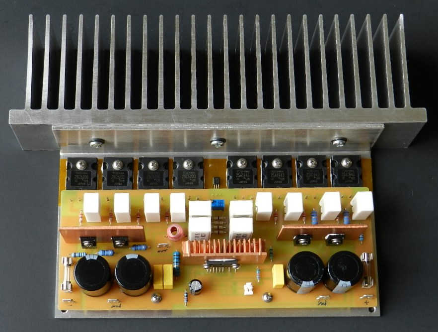
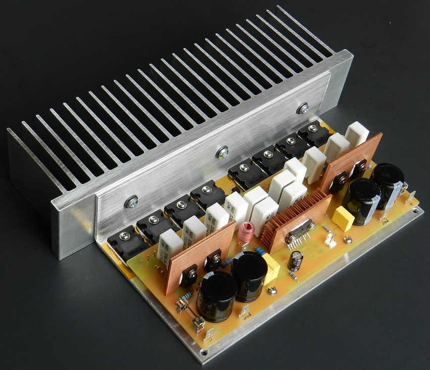
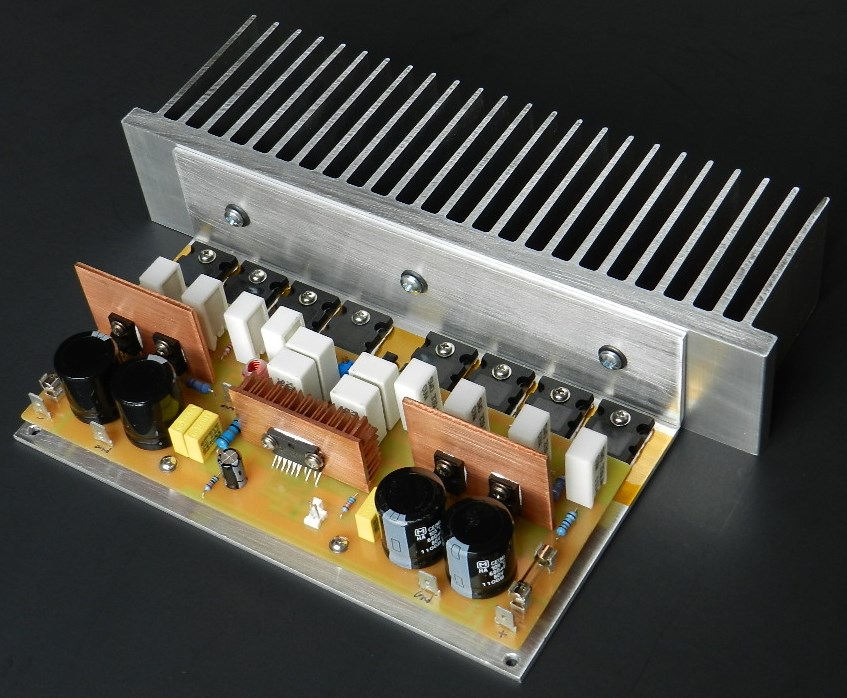
Project 21 is another power amplifier project with an LME49811 input stage driving a complementary feedback pair (CFP) power output stage operating in Class A mode. The outputs of LME49811 are connected to the paralleled Q1~Q2 and Q7~Q8 common-emitter driver stages. The output of the driver stages are coupled to the base resistors R1~R8 of the common-emitter configured power output stage transistors Q3~Q6 and Q9~Q12. The overall output of the amplifier is taken from the collectors of the power output transistors and also connected to the emitter of the driver transistors thru R21~R22 and R19~R20 resulting in unity gain and good linearity. Twelve radial power resistors were used in the power output stage transistors to improve overall stability of the amplifier. The power output of this project is about 60Wrms into an 8Ω load with a ±32VDC power supply. The recommended power supply would be a toroidal power transformer rated at 48VAC CT to 60VAC CT at 300VA or more and the capacitance value of the reservoir filter capacitors should be larger than 10,000uFd for one channel. A PCB-mounted 35Amp/1000V, KBU3510, is a good option to use as the bridge rectifier.
A huge extruded aluminum heat sink, larger than previous projects, was chosen to reduce thermal resistance and improve heat dissipation of the TO-264 packaged power output transistors operating in Class A. If you are interested about how to select a heat sink, then you should read this article from Aavid Thermalloy. The PCB prototype model was populated with SMDs around the LME49811 and Through-Hole components at the output stage. The schematic diagrams, BOM and PCB layout for Project 21 are available for free by request, as is, no warranty.
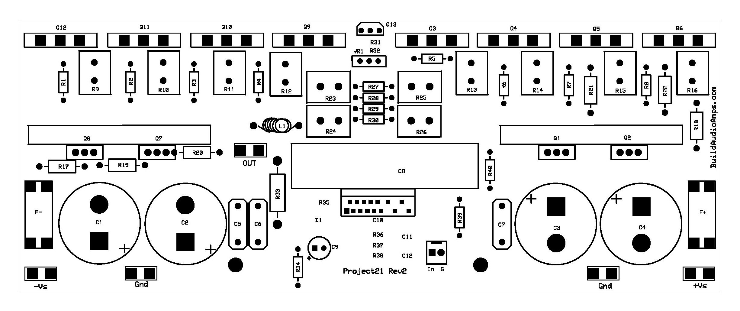 Project 21 Silkscreen and parts placement layer of PCB.
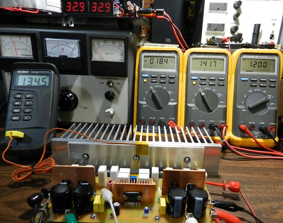
This is the fun part of building the project. Prepare 3 DMMs to measure the DC offset voltage, the voltage between collectors of PNP and NPN power output transistors and the idling current of the amplifier. Insert a jumper or shunt at the input of the amplifier. Do not connect any load or speaker at the output of the amplifier. The thermometer’s thermocouple sensor was attached to the middle of the PCB bracket and heat sink; to monitor and give you an idea of how high will the temperature rise during tests. The AC ammeter on the Variac reads within 2.5A throughout the duration of all tests.
Initially power the amplifier under test with ±32VDC. Adjust the Variac transformer to obtain ±32VDC from the power supply. The picture above shows the DC offset voltage about 18.4mV measured at the output of the amplifier, 141.7mV across the collectors of Q6 and Q12 and the idling current at 1200mA measured across the F+ fuse terminals. Adjust VR1 to obtain the idling current reading after a warm-up period of about 15 minutes. The temperature reading after 15 minutes was about 134.5° F. The adjustment for VR1 on the model unit was at minimum resistance. Switch the power supply to OFF immediately if you get different DMM readings. You may proceed with music test, if you obtain the same DMM readings. Project 21 was auditioned with the LM1036 tone control project and the sound quality was very enjoyable!
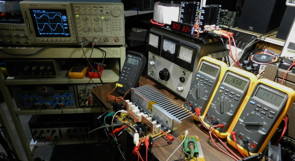
The next test procedure is optional, but if an oscilloscope, audio signal generator and 8Ω dummy load are available, you can measure the power output of the amplifier. Do not touch the heat sink or the dummy load during this test; they will get extremely hot! The dummy load’s temperature measured after the test was about 220° F.
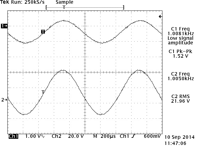
The power output was measured using an HP3312A Function Generator set at about 1KHz 1.52Vp-p sine wave output and connected directly to the input of the amplifier under test as well as CH1 test probe of the oscilloscope. An 8Ω/400Watt dummy load was connected at the output of the amplifier under test as well as CH2 probe of the Tektronix TDS520D 500MHz DPO. The amplifier produces 21.96Vrms across the 8Ω/400W dummy load or a power output of about 60Wrms, as shown in the TEK hardcopy picture on the right. The oscilloscope’s horizontal scale was adjusted at 200uS to verify for any visible clipping on its peaks. Higher power output is attainable with a 4Ω load.
It is recommended for this project to use a small cooling fan when installed in a confined enclosure. I’ve experimented using a fan during test by powering it on and off and have observed how the fan dramatically lowered the temperature and made the project thermally stable during normal listening level. An 80 mm fan rated at 12VDC and powered with a 5~8VDC power supply will make the fan very quiet with sufficient airflow to the amplifier project. Enjoy!