
Project 16
.jpg)
.jpg)
Project 16 is another power amplifier project that uses the LME49811 as the input stage and rated at 200Wrms into an 8Ω load with a ±64VDC power supply rails. Five pairs of T03P push-pull parallel configured complementary power output transistors were used to handle the high power supply voltage rails of the project. Two pairs of paralleled T0220 packaged complementary drivers were used and configured as emitter-followers. The circuit for this project is similar to Project 14 but all the driver transistors have emitter resistors and the complementary power output transistors are connected in parallel.
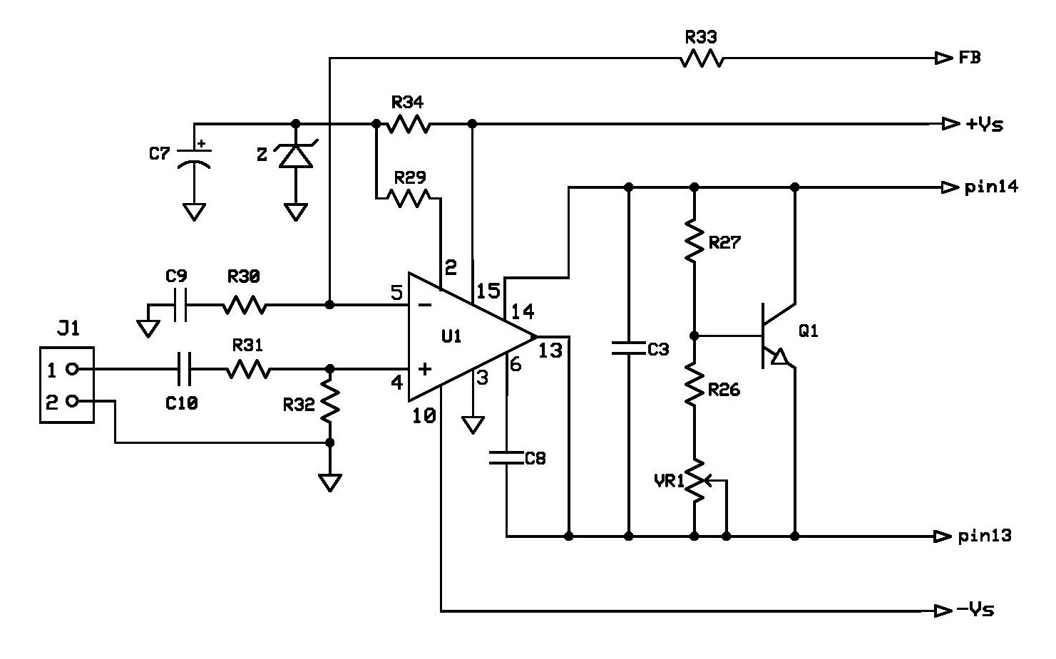
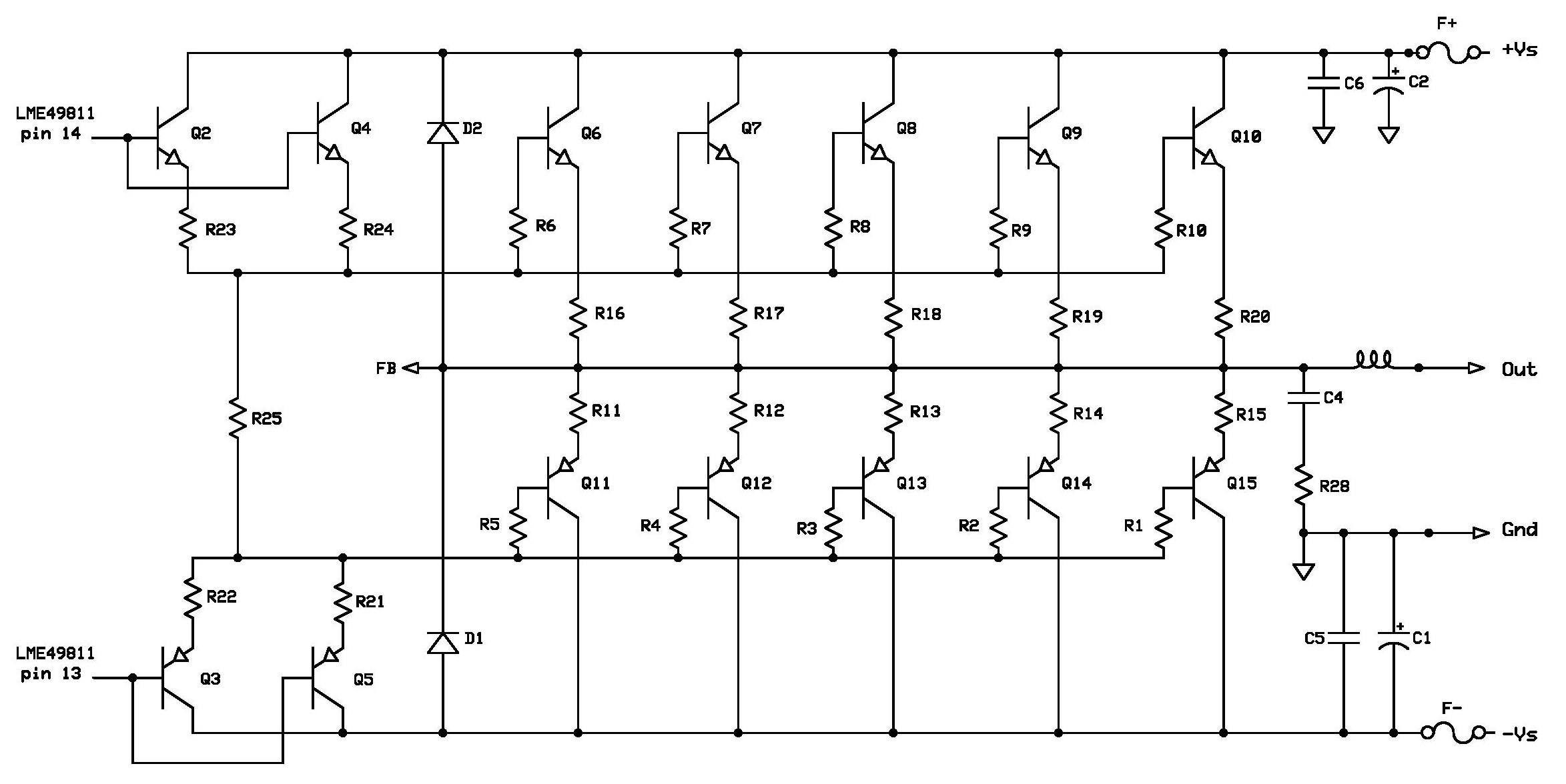
Schematic diagram of the input stage using an LME49811. Schematic diagram of the output stage.
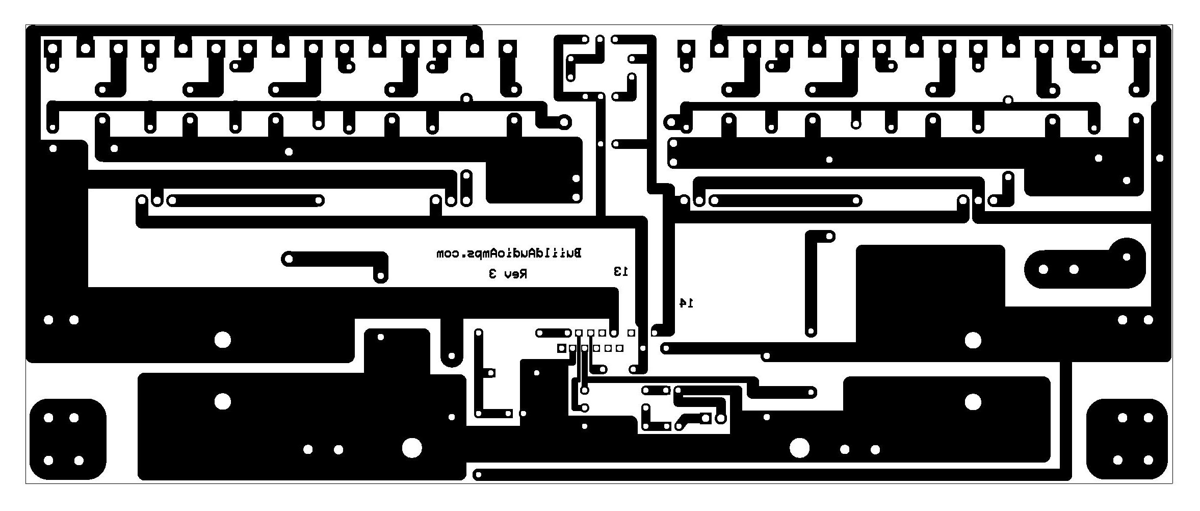
The PCB layout and Project 16 BOM are provided for free, as is, no warranty. The X-designated locations in the PCB are for 18AWG hook-up wires needed to connect one end of all the 5W radial power resistors together to the output inductor.
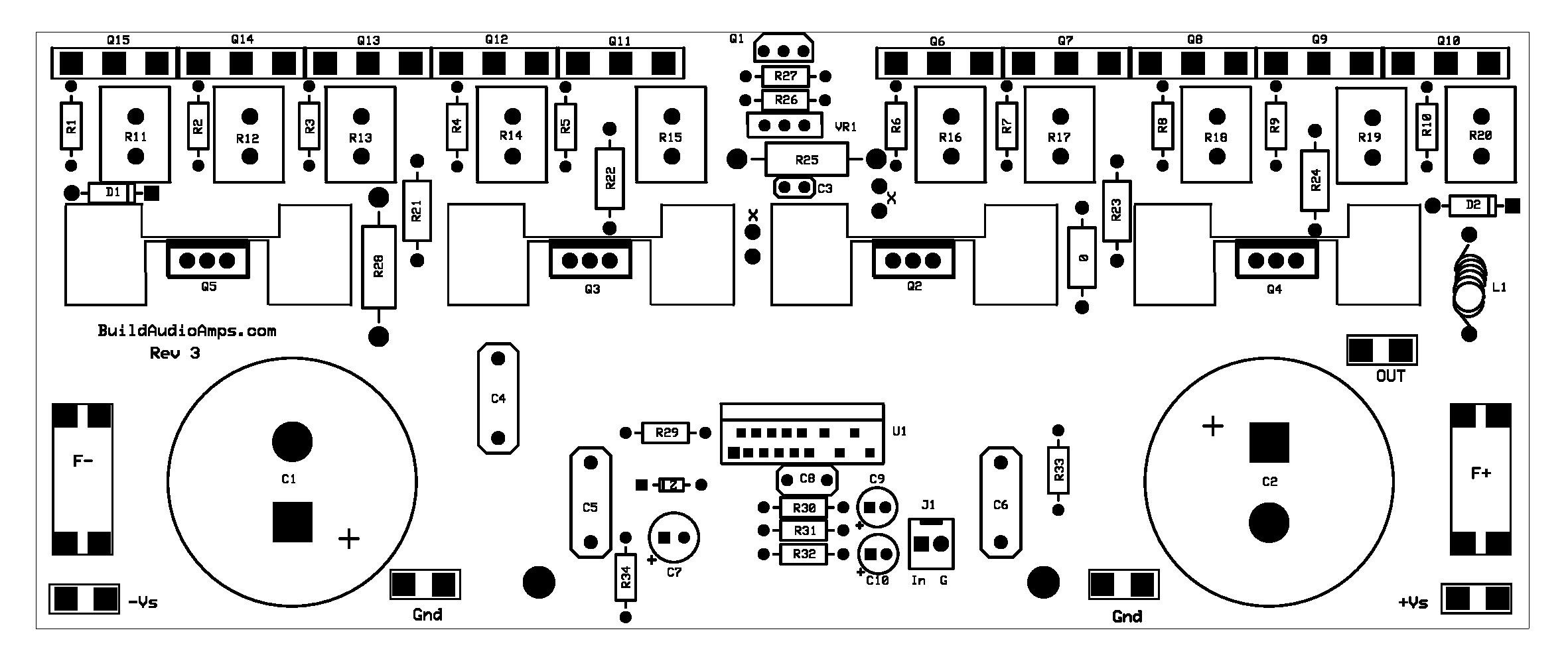
Silkscreen, pads and parts placement layer of PCB.
.jpg)
Here’s the fun part. I’ll be using a ±64VDC test power supply to power the amplifier under test; however, just to be safe; a ±24VDC can be used if available for initial tests. Install a jumper or shorting shunt at the input and do not connect any load at the output of the amplifier. The DMM on the left side of the picture is reading the DC offset voltage of the amplifier at about 1.4mV. The DMM in the middle is measuring the voltage drop of R15 and R20 at about 3 to 5mV, adjust VR1 to get this value after a warm-up period of about 10 minutes. The DMM on the right side of the picture is reading the current at F+ fuse terminals at about 55 to 70mA. If you obtain about the same readings as shown, proceed with music test. I’ve paired the LM1036 tone control with this project and it did not disappoint!
.jpg)
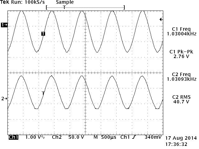
This next test will measure the power output of the amplifier project and is optional. Be careful not to touch the amplifier’s heat sink or the dummy load, they will get extremely hot! The function generator is set for a sine wave output at about 1KHz 2.76Vp-p and connected directly to the input of the amplifier under test. The power amplifier produces 40.7Vrms across an 8Ω/400W dummy load or about 207 watts with higher power output attainable when loaded with 4Ω or 2Ω. The Tek hardcopy picture is showing the power output of the project with barely visible clipping on its peaks. Enjoy!
.jpg)
.jpg)
![]()