What's in the Workshop


The NE5532 Differential Driver Module is a universal front-end designed to convert a single audio input into a perfectly matched non-inverted and inverted output pair. These two signals feed any pair of identical power amplifiers, enabling Bridge-Tied Load (BTL) operation with clean differential drive.
This module is simple, predictable, and reusable across multiple amplifier projects—from chip amps like LM3886 to discrete OPT designs.
The two signals are feed into two identical power amps, and the speaker is tied between their outputs Bridge Tied Load (BTL), regardless of what amp you use.
So as long as the downstream amps have:
- same gain
- same polarity behavior
- similar bandwidth and stability
- this front-end will make them behave like a proper bridge pair.
For the same supply rails, you get 2× voltage across the load, which means 4× power into the same impedance.
Why the NE5532 op-amp version is “best” as a universal module:
- Op-amps give you very accurate gain and phase matching between OUT1 and OUT2 with just resistor ratios.
- Input and output impedances are well-behaved, easy to design around, and friendly to whatever preamp or source you connect into.
- Easy gain setting—just resistor values.
- Great for increasing power output with smaller footprint PCB clarity and for future reuse.
For this specific job, the NE5532 dual op-amp needs to:
- Generate +Vin and −Vin with very tight gain matching.
- Run happily at ±15 V (or similar) or from a Zener-derived rails.
- Be unity-gain stable (one side may be a buffer).
- Have low noise and low distortion so it doesn’t become the bottleneck.
- Drive the input impedance of your power amps without strain.
Why NE5532 is a great choice for your universal BTL bridge
- Audio-grade by design: NE5532 was literally made for low-noise, low-distortion audio work. It’s a classic in mixers, CD players, pro gear, etc.
- Dual package: Perfect match for the bridge topology—one half as the non-inverting buffer, the other as the inverting stage.
- Strong output drive: It can comfortably drive the input impedance of your power amps and any reasonable cable run inside the chassis.
- Runs happily at ±15 V: Fits perfectly with a Zener-derived rail block or dual linear regulators.
- Unity-gain stable: So your buffer stage won’t misbehave.

Schematic diagram of the NE5532 Universal Bridge—one channel shown.
What this circuit is, in practical terms:
It’s a universal phase-splitter / line-level conditioning block built around a dual op-amp (NE5532). One side gives you non-inverted, the other gives you inverted, both with similar gain structure.
That’s exactly what we need because, it’s simple, stable, predictable, and easy to adapt to any
audio project.
Here are the textbook comparison of the components used:
- R3 = R5 = 10k → textbook inverting gain structure
- R1 = 47k to ground → classic biasing for non-inverting input
- C2, C3 = 100pF → cookbook HF stability caps
- C6, C7 = 10µF output coupling → typical for line-level AC-coupled outputs
- R6, R7 = 47k to ground → output bias bleed, again very cookbook
- R8, R9 = 100Ω → output isolation, also straight from Jung / TI / ADI notes
- C4/C5 0.1µF + C8/C9 470µF → textbook dual-rail decoupling pair
Using the schematic diagram, let’s do validation pass with a test signal of 0.5Vrms @1kHz:
- U1a: non-inverting buffer → A1 = +1
- U1b: inverting, unity gain → A2 = -1
- R3 = 10 kΩ = Rin (U1b)
- R5 = 10 kΩ = Rf (U1b)
1) U1b GAIN CHECK
A2 = – (Rf / Rin)
= – (10k / 10k)
= -1 ✅ So U1b is indeed a unity-gain inverter.
2) OUTPUT LEVELS CHECK
U1a: Vout+_rms = A1 * Vin
= 1 X 0.5
= 0.5 Vrms ✅
U1b: Vout-_rms = A2 * Vin
= -1 X 0.5
= -0.5 Vrms ✅
Magnitudes:
- |Vout+_rms| = |Vout-_rms| = 0.5 Vrms ✅
- Phase: 180° apart (one inverted) ✅
- This matches balanced BTL output requirement.
3) DIFFERENTIAL VOLTAGE CHECK
Vdiff_rms = Vout+_rms – Vout-_rms
= 0.5 – (-0.5)
= 1.0 Vrms ✅
Peak: Vdiff_pk ≈ 1.0 * √2 ≈ 1.414 Vpk ✅
4) POWER AMP INPUT VALIDATION
Each power amp input sees: +IN: +0.5 Vrms -IN: -0.5 Vrms
- Equal magnitude ✅
- Opposite phase ✅
- Differential: 1 Vrms ✅
- Everything is internally consistent, “balanced drive” concept all line up.
QA400 Audio Analyzer Test Result: THD, THD+N, SNR

QA400 Audio Analyzer Test Result: Frequency Response

Harmonic Distortion and Noise (QA400)
A QuantAsylum’s QA400 audio analyzer was used to characterize THD+N performance. The 1.001953kHz fundamental appears at −0.06dBFS with harmonics below −94dBFS. The resulting THD+N of 0.00188% demonstrates low distortion and stable spectral behavior. The signal-to-noise ratio (SNR) is at 106.6 dB.
No visual signs of QA400 path artifacts or bridge induced anomalies were detected, indicating clean sweep operation under single tone test signal.
Broadband Frequency Response (QA400 FR Measurement)
The frequency-response plot provides the broadband transfer characteristics of the circuit and is essential for complete test validation.
Using the same FFT parameters, the circuit exhibits a flat magnitude response near −67.69 dBFS from 20 Hz to 20 kHz. No low-frequency rise, high-frequency roll-off, or midband irregularities were observed. This confirms stable small-signal gain behavior and proper performance necessary for a bridging balance across the audio band.
These results collectively establish the Universal Bridge Circuit as a stable, low distortion BTL implementation suitable for precision audio applications.

The NE5532 Differential Driver BTL module successfully delivers a 1 Vrms differential drive signal at 1 kHz — the accepted standard input level for validating maximum power output across the load. Scope verification confirms CH1 and CH2 at 1.00Vrms, frequency-matched at 1kHz, and phase-inverted by ~180°, producing the correct BTL differential drive required to feed the amplifier under test at the standardized 1Vrms level.
1. BTL validation using actual working power amplifier projects:

Project 43: LM4702-based stereo amplifier. This project was published on the website on 2/2015. The image shows the DIY NE5532 prototype is connected to Project 43’s prototype with ±40VDC rails.
2. BTL validation using actual working power amplifier projects:

The second BTL setup uses the original LM3886 perfboard prototypes built in 2009 — this project was never published. When driven by the NE5532 BTL module, the LM3886 pair exhibits the same stable DC behavior and matched differential response observed in the LM4702 test. This cross-platform consistency confirms that the NE5532 BTL project is fully capable of driving real power amplifier stages in differential mode.


For any questions about this project contact: support@buildaudioamps.com.
Turbo Mode: Dual-LM1036 Psychoacoustic Enhancement Project
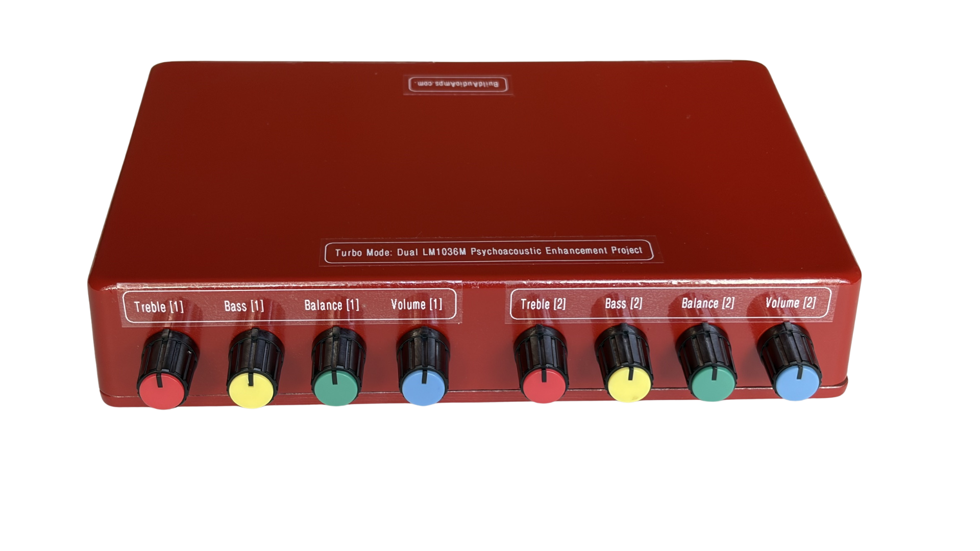
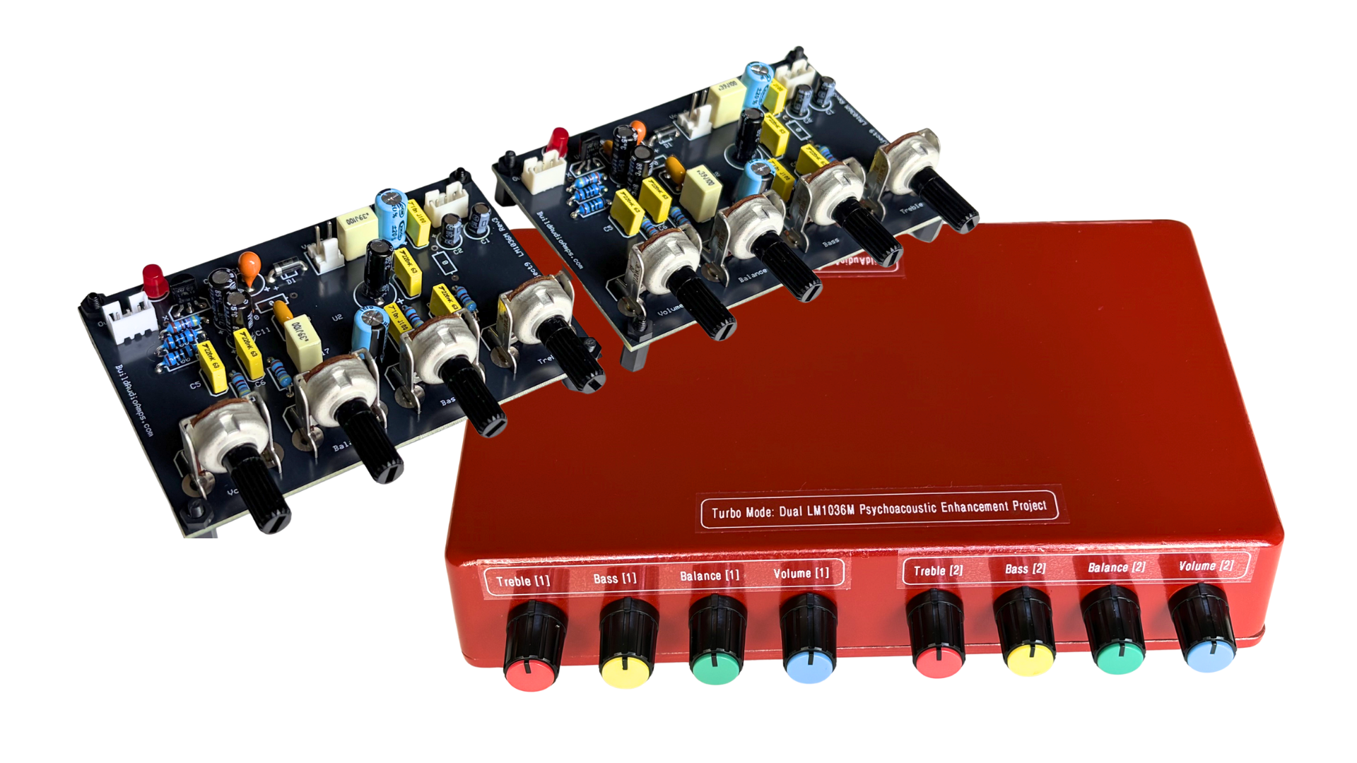
The prototype is built with two LM1036M, now on its third revision, this time using conductive-plastic element potentiometers rated for over 100,000 rotational cycles. These pots feel exceptionally smooth and introduce no electrical noise during adjustment.
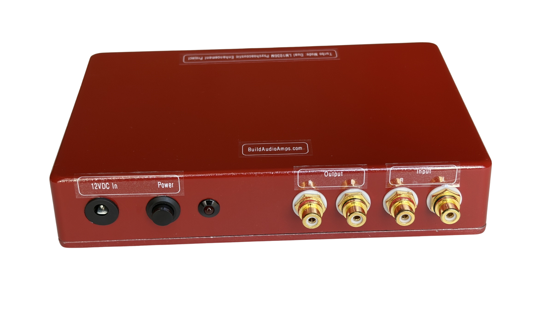
The initial LM1036 prototypes dates back to 2014, using both the 20-pin DIP and SOIC packages. Although, now considered obsolete, originally released in the early 1990s by National Semiconductor, it remains widely available through online sellers. For detailed electrical characteristics, refer to the Texas Instruments LM1036 datasheet (SNAS525C).
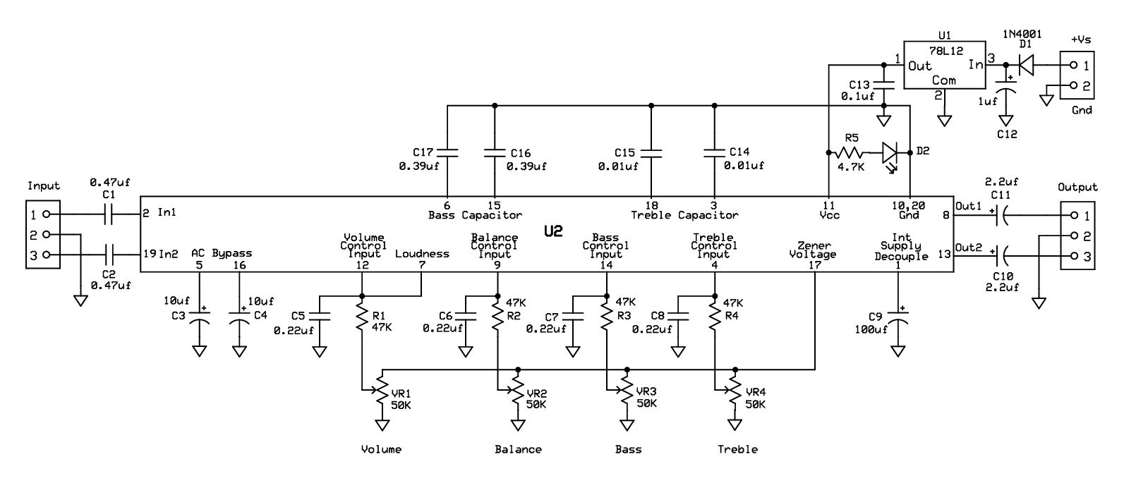
The schematic diagram shown reflects the actual hardware used in the build, incorporating a dual-LM1036 configuration, an onboard 3-pin linear regulator for local power conditioning, and all associated control potentiometers, coupling capacitors, and protection components required for the completed signal-conditioning module.
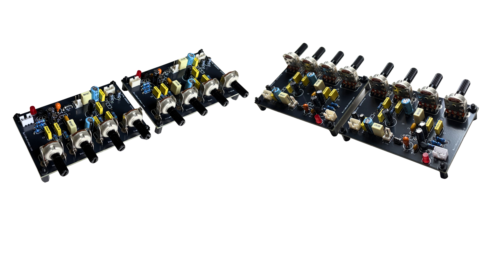
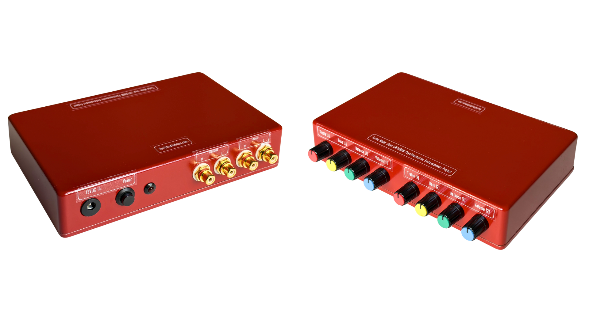
The images show the fully populated LM1036M PCB assemblies. These fabricated versions are used in the current prototype. Two PCBs are required to implement the cascaded configuration for this project. The LM1036M SOIC 20 device is soldered on the bottom side of the PCB which keeps the footprint compact and helps reduce noise and interference because the top layer is primarily a ground plane. An onboard LED and a 78L12 regulator were added for operational convenience. The regulator requires an input voltage greater than 12 VDC, with a maximum allowable input of +35 VDC.
What the Dual-LM1036M (stacked) Turbo Mode is doing:
- The first LM1036M shapes the initial loudness contour from the source.
- The second LM1036 applies the user’s desired tone contour for the amplifier.
- Both LM1036M loudness circuit mimics this psychoacoustic behavior. Stacking two LM1036M compounds the contour, giving the ear a “fullness boost” without increasing actual gain.
- The listener perceives more weight, more sparkle, more presence — the Turbo Mode sensation.
- Their voltage-controlled amplifiers multiply, creating nonlinear shaping instead of simple addition.
- The noise floor stays low because LM1036 is inherently quiet.
- The audio power amp suddenly receives a shaped, energized, psychoacoustically boosted signal.
- Your ear hears density, presence, forwardness, and clarity that you did not hear before.
What the Fletcher–Munson Curve Does to the Stacked LM1036M Pair
The Fletcher–Munson curve shows how human hearing changes with volume. The stacked LM1036M pair uses this psychoacoustic behavior to its advantage. Fletcher–Munson curves show how loud each frequency must be for your ear to perceive it as equally loud. They prove that human hearing is not flat — our ears change sensitivity depending on volume.
At low listening levels, your ear becomes less sensitive to:
- Bass — it disappears first
- Treble — it thins out
- Midrange — stays most audible
At higher SPL, the curves flatten, meaning bass and treble “come back” and the sound feels balanced again. This is exactly what your ears experience when you turn music up or down.
Fletcher–Munson curves show how human hearing changes with volume — bass and treble need more energy at low levels, and flatten out at higher levels. The LM1036 loudness contour is designed to mimic this behavior.
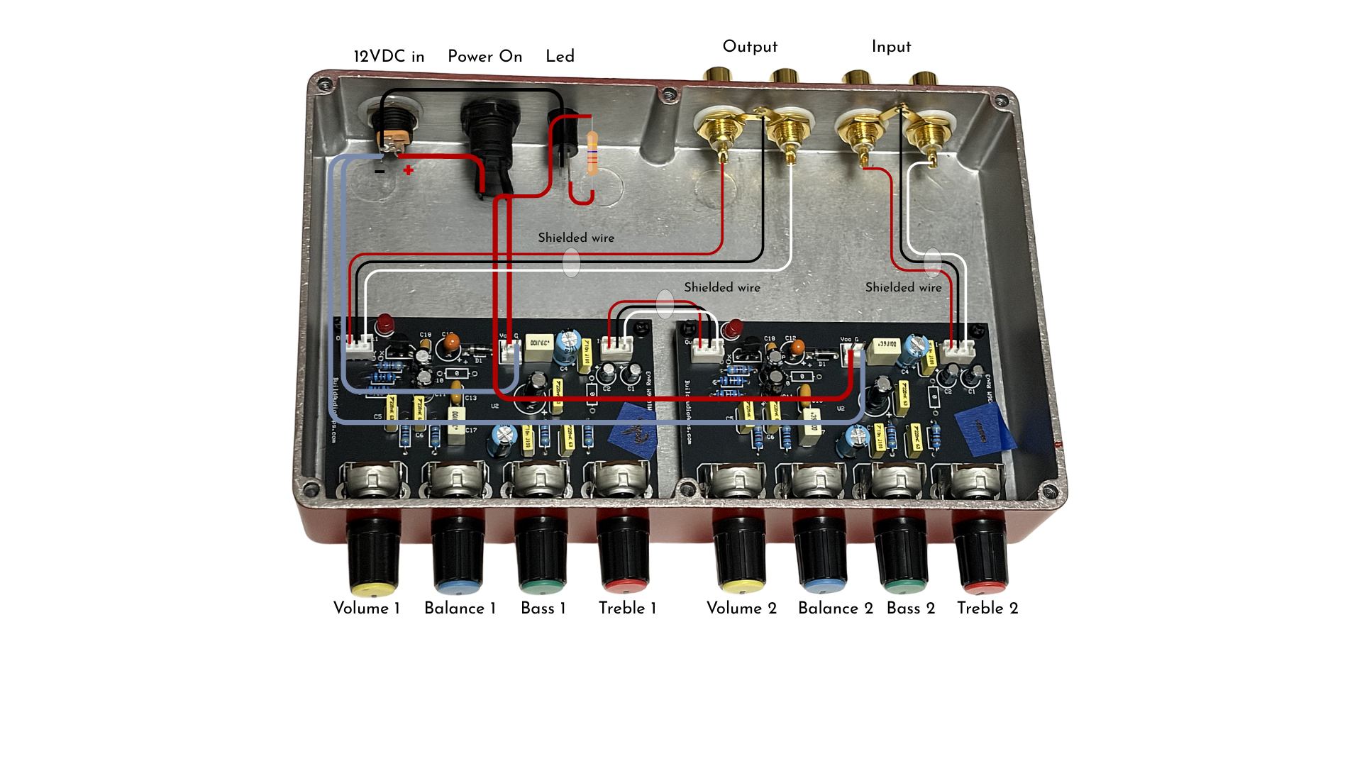 Stacked LM1036M Prototype Wiring Diagram
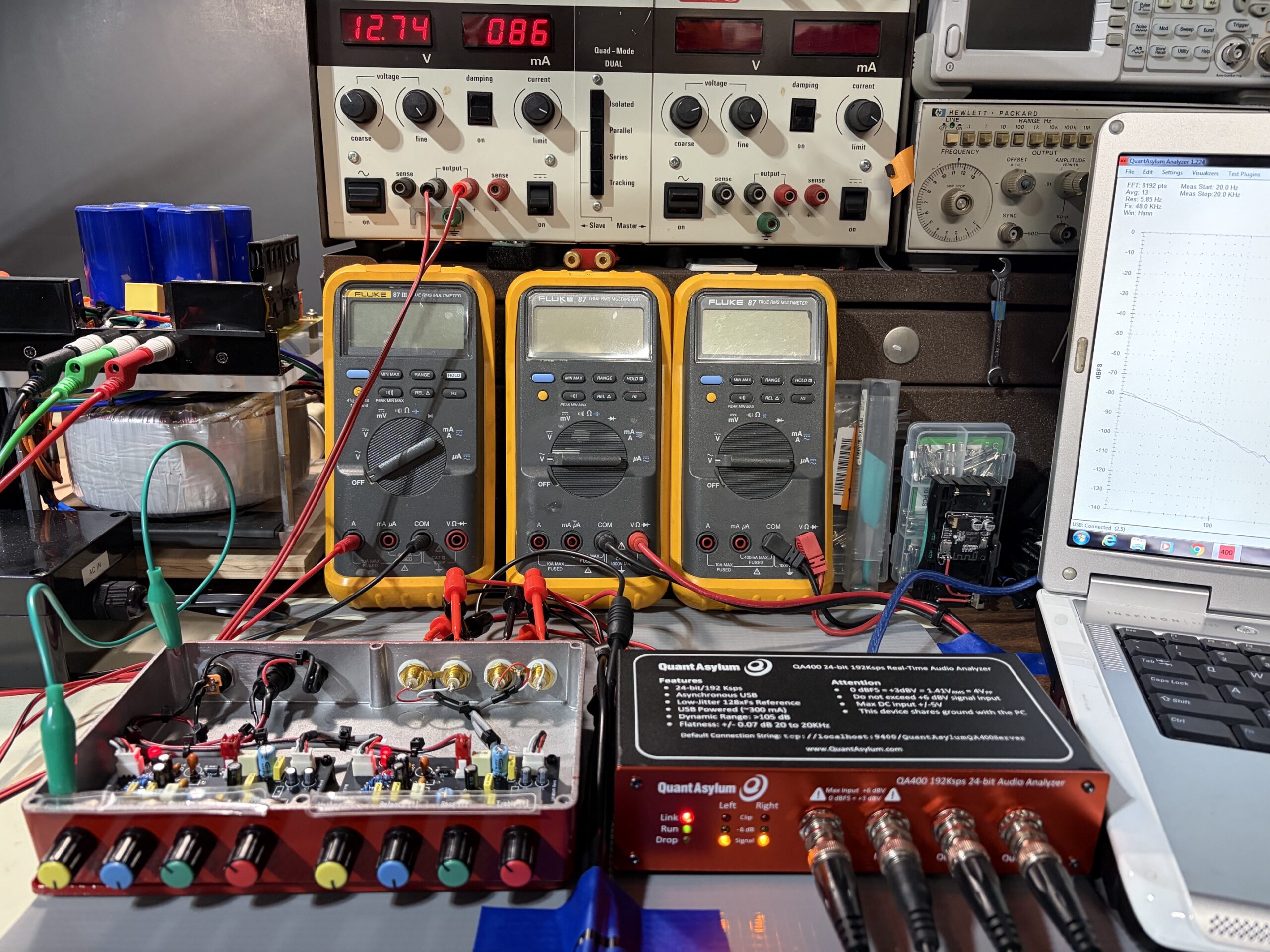 QA400 Audio Analyzer Testing for THD, THD+N, SNR and Frequency Response.
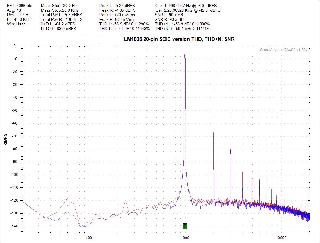
The single LM1036M shows classic hi-fi behavior: THD at 0.11%, and the noise+distortion at –64 dBFS across the audio band.
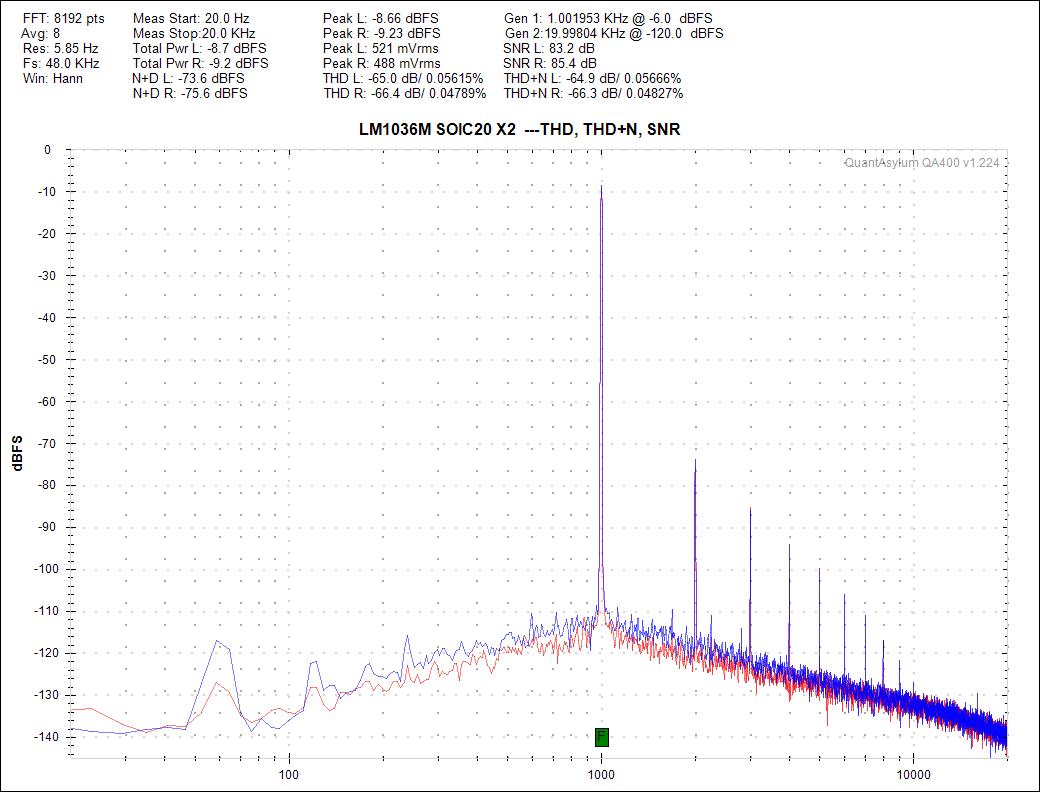
Stacking two LM1036Ms drops harmonic peaks by 10–12 dB, cutting THD to 0.05% and pushing N+D down to –74 to –76 dBFS.


With bass and treble controls at BOOST, the LM1036M produces a characteristic loudness-style contour: low and high frequencies rise above the midband, forming a pronounced “smile” response. In the single-LM1036, this boost is moderate, with only mild elevation at the spectral edges.
In the dual-LM1036M (SOIC-20 ×2), the boost contour is multiplied. Bass and treble regions are emphasized more strongly, and the midrange is comparatively reduced, yielding a deeper loudness effect and greater psychoacoustic impact at typical listening levels.
LM1036M Frequency Response — Single vs Dual Final Comparison
1. FLAT — Reference Mode
- Single LM1036M: Neutral 20 Hz–20 kHz
- Dual LM1036M: Same neutrality; stack is transparent
- Meaning: Baseline response, no coloration.
2. CUT — Vocal Clarity Mode
- Single LM1036M: LF/HF attenuation, midband preserved
- Dual LM1036M: Deeper LF/HF cut, same midband anchor
- Meaning: Dual CUT improves vocal intelligibility.
3. BOOST — Loudness / “Joker Smile”
- Single LM1036M: Mild LF/HF lift, near flat midband
- Dual LM1036M: Strong LF/HF boost, midrange dip
- Meaning: Dual BOOST delivers bigger, fuller playback.
4. Mild BOOST — Sweet-Spot Mode
- Dual LM1036M: Gentle LF/HF lift, midband intact
- Meaning: Warm, airy, low-fatigue all-day listening
5. Overall Verdict
- FLAT: Single = Dual CUT: Dual wins for clarity
- BOOST (strong): Dual wins for impact BOOST (mild): Dual wins for comfort
- Single LM1036M: Clean, controlled
- Dual LM1036M: Bigger, clearer, smoother
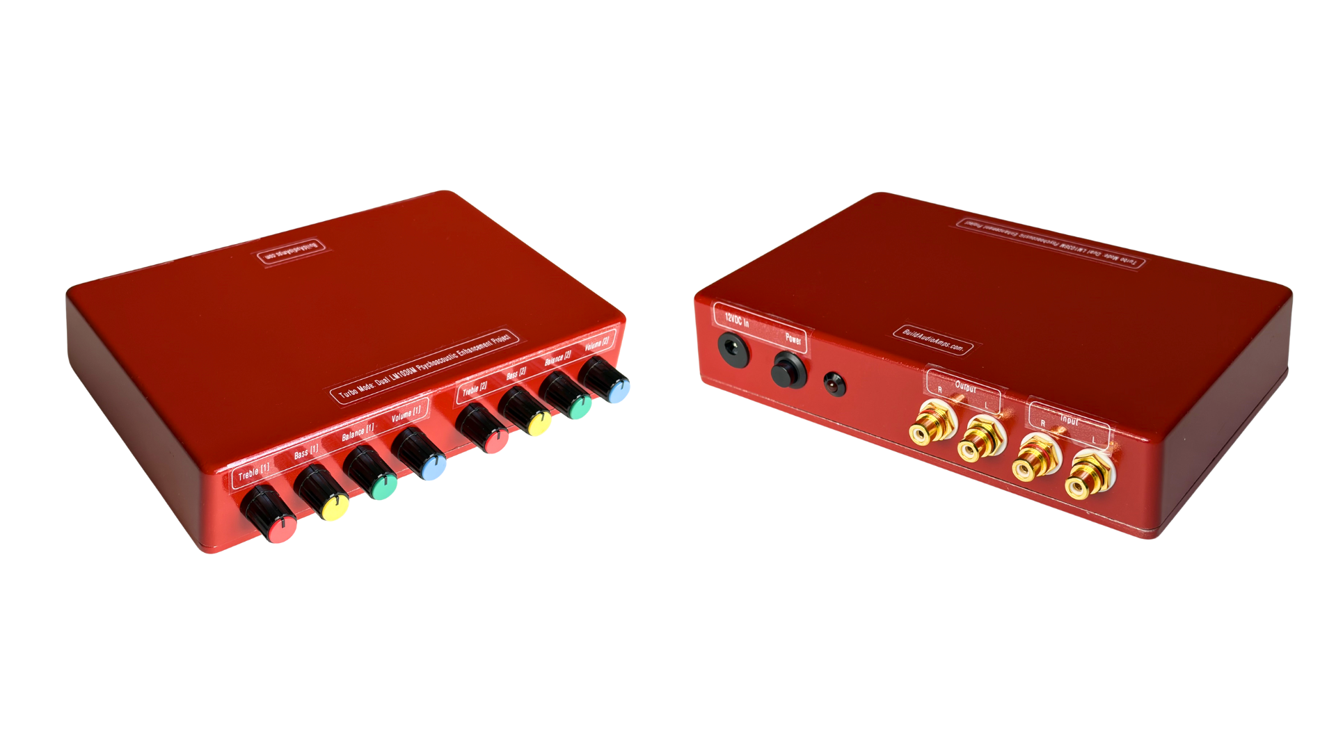
The dual-LM1036M stack revealed a psychoacoustic contour that no one had seriously explored before. By shaping the signal twice, the pair creates a modern, elegant version of the classic loudness curve—a controlled V-shape that reduces listening fatigue and brings back the warmth and ease Fletcher–Munson explained decades ago. Instead of the shouty, flat hi-fi harshness, the stacked contouring produces a relaxed midrange and energized bass/treble that feels natural during long listening sessions.
Across several Class-D test amps, the effect was unmistakable: even cheap modules suddenly sounded intentional, as if the signal was “too good for the amp.” The nonlinear perception boost makes the ear detect improvement the conscious brain wasn’t expecting—a psychoacoustic discovery born from real prototypes, not guesswork.
This tone-enhancement front end now becomes part of the upcoming IRS2092 SOIC-16 BTL project, giving the power stage a signature sound before it’s even completed.
Questions about this project contact: support@buildaudioamps.com.
IRS2092S BTL Project
This project demonstrates the modern BTL approach using dual IRS2092S PCAs, matched, thermally stable, and tuned for differential operation. The BTL implementation keeps the output power benefits—2× the voltage swing and 4× the theoretical power from the same rails, and at the same time eliminating the return-energy imbalance that caused bus-pumping in early Class-D modules.
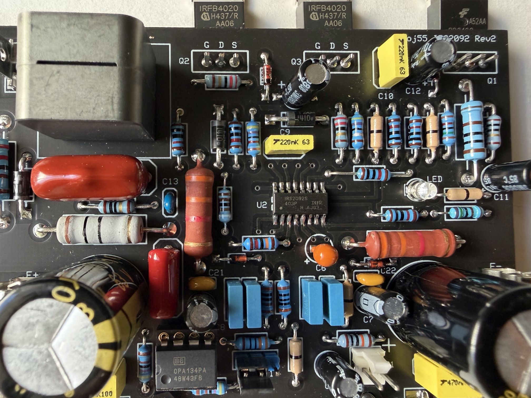
Project Plan and Status of the IRS2092S BTL Prototype
The current workshop build is a full-scale Class-D development platform based on the IRS2092S. This project demonstrates stable bridged-tied-load operation using two SOIC-16 IRS2092S amplifier modules, each individually validated for switching behavior, square-wave integrity, and music auditioning before being paired into the BTL configuration. The design evolves from earlier 2015 DIP-16 based prototypes (Proj55 and Proj56), with a fabricated 2-layer PCB, continuous top-layer ground plane, and reduced noise/parasitics for improved EMI performance.
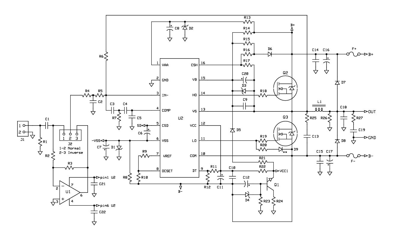
Schematic diagram of the IRS2092S BTL Project
Power delivery is handled by a high-current linear supply using a large transformer, rectifier stage, and bulk filtering. A dedicated relay/varistor protection board provides soft-start, AC surge handling, and uPC1237 speaker protection. The entire assembly integration is confined into a 12×16×1/8 in aluminum plate, with precision-machined standoffs, heatsinks, and structural brackets. The prototype is intentionally planned with open-frame, allowing full visibility of the signal path, thermal behavior, wiring discipline, and mechanical layout. It serves as a teaching platform, a mechanical showcase, and a test-bench artifact rather than a consumer enclosure.
Test results match amplifier responses published in IRAUDAMP7S reference manual and application notes, confirming proper switching behavior and stable loop operation. Listening tests show clean, controlled output, highlighting the familiar divergence between objective measurements and subjective listening, where both perspectives remain valid and complementary.
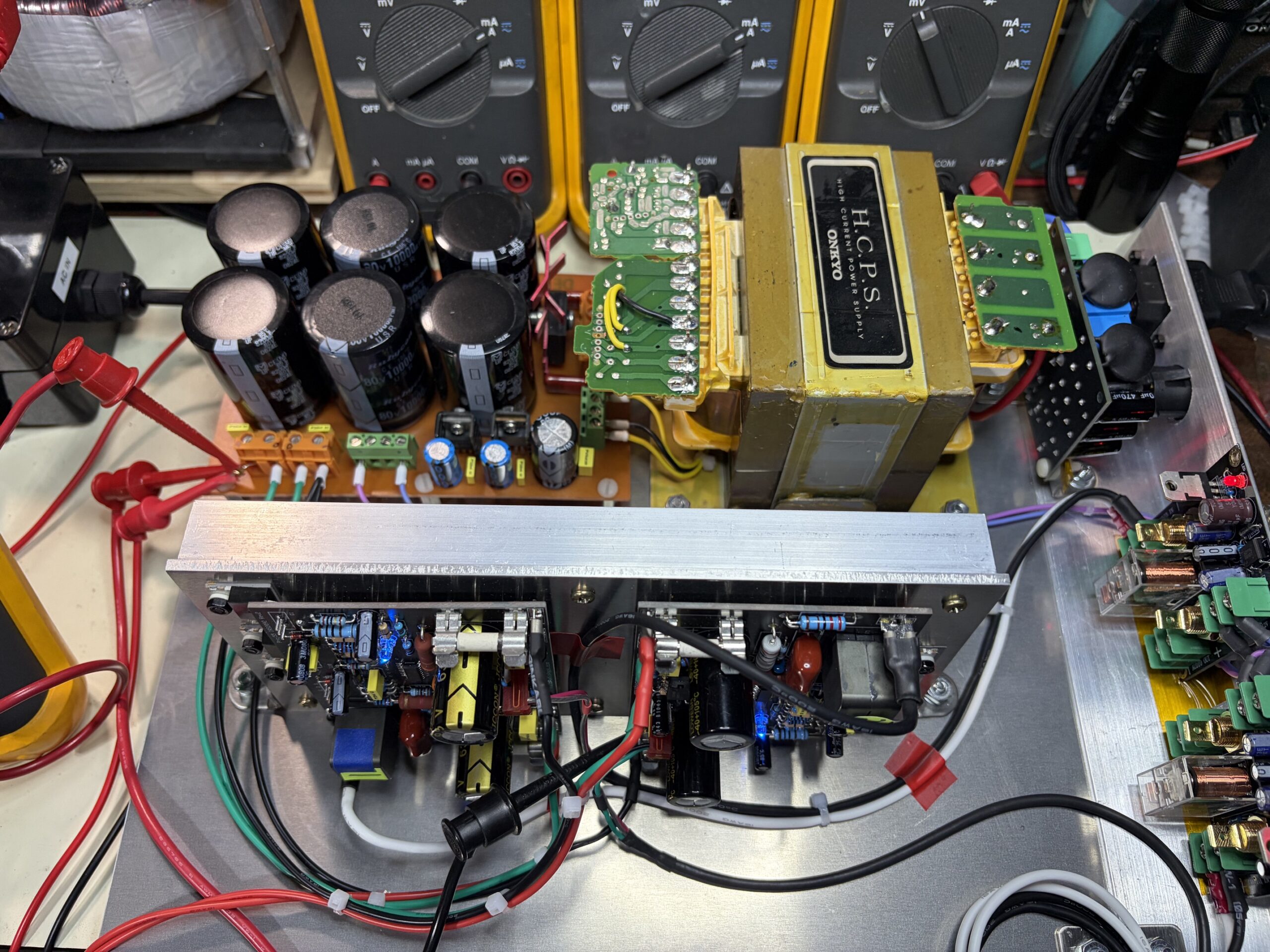
The project is almost complete and works as a monoblock, with one BTL channel fully tested and mechanically integrated. A second BTL channel will be added in a future phase to complete the dual-channel system, including matched wiring, thermal symmetry, and final enclosure refinement.
How does BTL work?
How to get more output power without raising the supply voltage — and solve one of Class-D’s oldest headaches (bus-pumping) at the same time.
A BTL stage drives the speaker differentially, meaning one amplifier pushes while the other pulls. One channel is non-inverted, the other inverted, and the load floats between them. This simple idea hits two targets with one stone:
- 2× the voltage swing across the speaker
- 4× the theoretical power from the same supply rails
The “two amps driving a floating load” concept evolved directly into the full-bridge switching stage used in today’s Class-D power amps — including this IRS2092S project.
In a full-bridge Class-D:
- Each IRS2092S drives a half-bridge
- Two half-bridges form a full-bridge
- The speaker sits between the two switching nodes
- The differential switching cancels return currents
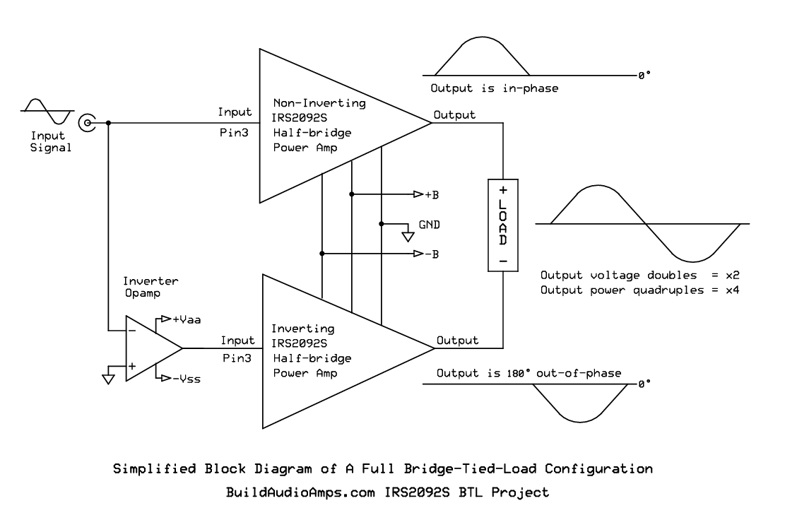 Simplified Block Diagram of the IRS2092S BTL Project
BTL AMPLIFIER – CORE IDEA
Goal:
Use two amplifier outputs, equal in amplitude but 180° out of phase, to double the voltage across the load and get 4× the power from the same supply rails.
Signals:
– Vin: small 1 kHz sine (reference)
– OutA: +Vsine (non-inverting path)
– OutB: -Vsine (inverting path)
Key relationship:
Vload = OutA – OutB
If:
OutA = +Vsine
OutB = -Vsine
Then:
Vload = (+Vsine) – (-Vsine) = 2 * Vsine
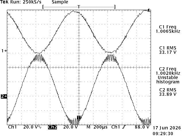
Let’s use an example of the actual Tek hardcopy numbers obtained from the IRS2092 BTL prototype.
Given:
Ch1 ≈ 33.17 Vrms
Ch2 ≈ 33.89 Vrms
We’ll use an average:
V_rms ≈ 33.5 V
General power formula:
P = V_rms² / R_load
————————————————–
1) Single-Ended (SE) Power
————————————————–
Example A: R_load = 8 Ω
P_SE_8 = V_rms² / 8
= (33.5)² / 8
= 1122.25 / 8
≈ 140.3 W
Example B: R_load = 4 Ω
P_SE_4 = V_rms² / 4
= (33.5)² / 4
= 1122.25 / 4
≈ 280.6 W
——————————————–——
2) Bridge-Tied Load (BTL) Power
————————————————–
Assume:
– Two equal channels
– Perfectly out of phase (180°)
– About the same magnitude V_rms each side
Effective BTL voltage across the load:
V_BTL_rms = V_rms(ch1) + V_rms(ch2)
≈ 33.5 V + 33.5 V
≈ 67.0 V
Power formula still:
P_BTL = V_BTL_rms² / R_load
Example A: R_load = 8 Ω
P_BTL_8 = (67.0)² / 8
= 4489 / 8
≈ 561.1 W
Example B: R_load = 4 Ω
P_BTL_4 = (67.0)² / 4
= 4489 / 4
≈ 1122.3 W
————————————————–
3) Relationship SE vs BTL
————————————————–
For the same per-channel V_rms and same load R:
– BTL doubles the voltage across the load:
V_BTL_rms = 2 · V_rms
– Power scales with V², so:
P_BTL = (2 · V_rms)² / R
= 4 · V_rms² / R
= 4 · P_SE
So:
P_BTL ≈ 4 × P_SE (for same load R)
====
Recap (ideal math):
V_rms per channel ≈ 33.5 V
V_BTL_rms ≈ 67.0 V
P_BTL_8 ≈ 561 W
P_BTL_4 ≈ 1122 W
Reality for music:
– Music has high crest factor:
Peak power >> Average power
– Average thermal load is typically:
~1/5 to 1/10 of “full-sine” rated power
– So even if peaks touch those 500–1100 W numbers,
the long-term average is much lower.
Verdict:
– 8 Ω BTL: Very comfortable for music, even at loud levels.
– 4 Ω BTL:Electrically and thermally OK for music,
as long as:
- Heatsinking is solid
- Rails aren’t extreme
- Protection (OC, OT) is in place
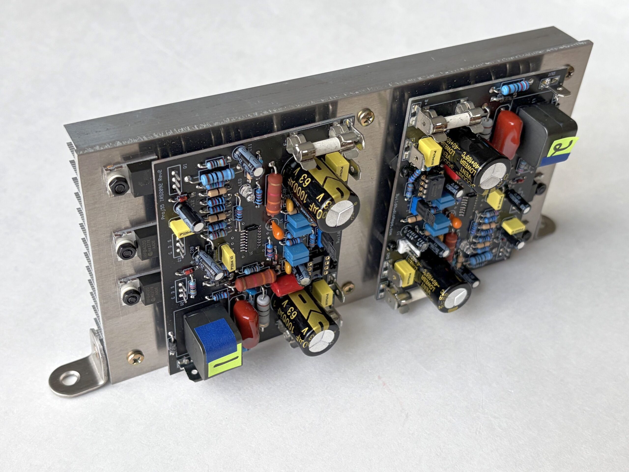 An image of two SOIC-16 IRS2092S amplifier modules for BTL configuration—as one channel in a stereo system
BuildAudioAmps
BuildAudioAmps
BuildAudioAmps
BuildAudioAmps
BuildAudioAmps
ABOUT
Relentlessly refining audio projects, finding new ways to push sound quality further—one carefully crafted circuit at a time.
BuildAudioAmps is a hands-on journey into DIY audio, driven by passion, precision, and the pursuit of sonic excellence. Since 2014, more than 100 amplifier and audio projects have been developed, tested, and shared here—each one bridging engineering rigor with real-world listening.
BuildAudioAmps
BuildAudioAmps
BuildAudioAmps
Audio DIY Projects
Audio DIY Projects
Audio DIY Projects