
Project 4
Project 4 is another classic audio amplifier circuit that is rated at 70 watts into an 8Ω load. It uses 2 pairs of 2SC5242/2SA1962 complementary power transistors and the main power supply rails are ±44VDC. An op-amp servo circuit controls the DC offset voltage of the amplifier. I have drawn the schematic diagram to match with the actual Part Ids that were populated in the circuit board. A few SMT components were combined with the rest of the thru-hole components to make it more interesting and enjoyable to build.
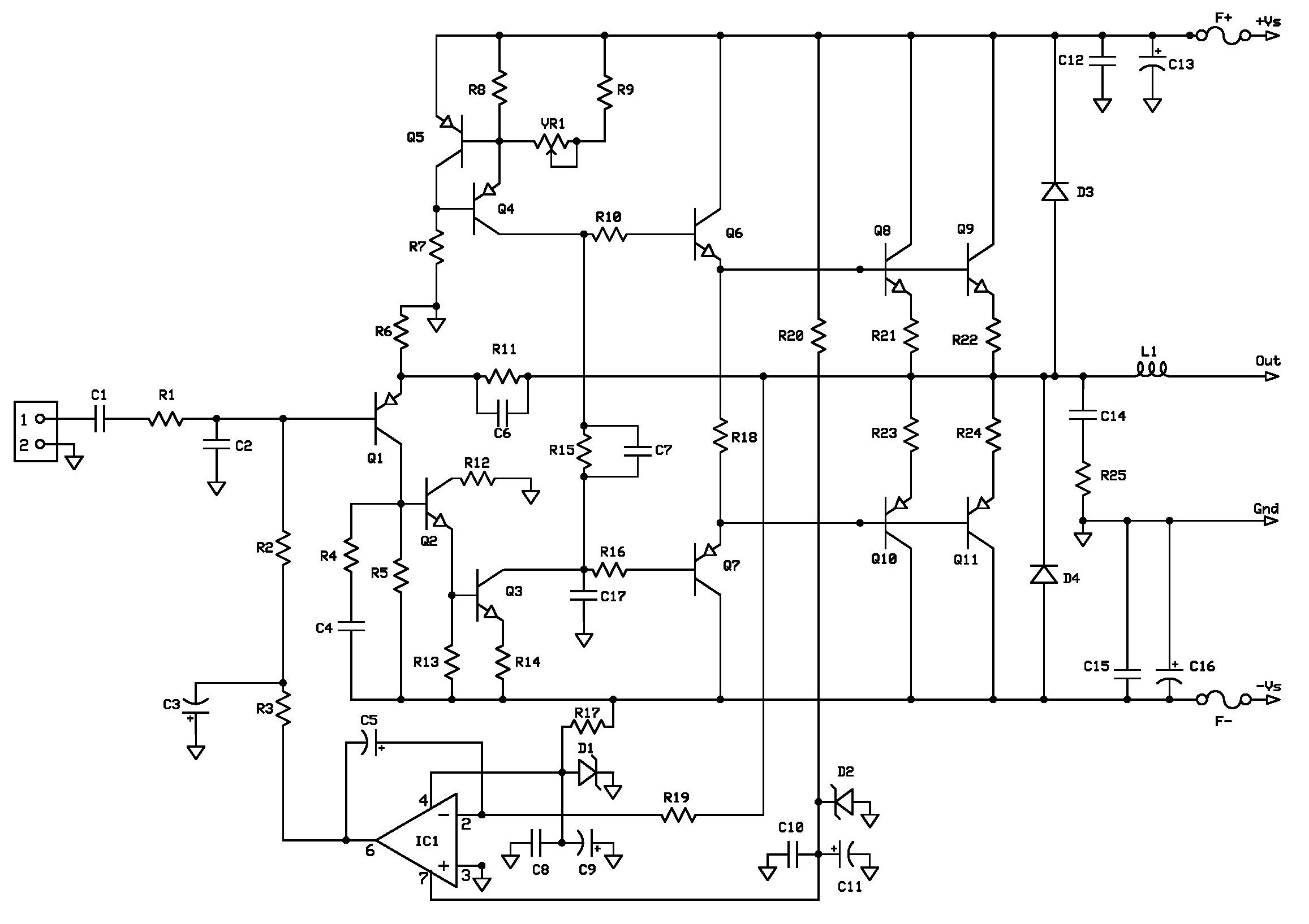
Schematic Diagram of Project 4
The amplifier uses a single transistor input stage Q1 instead of the more common long-tailed differential amplifier input circuit, similar to a vintage “The Brute70” solid-state amplifier project. The input signal is applied to the base and the feedback signal coming from the output by way of R11 and C6 to the emitter of Q1. The DC offset voltage signal from IC1, configured as a DC servo, is also connected to the base of Q1. An emitter follower Q2 acts as a buffer and Q3 as a Class A voltage amplifier stage, current-sourced by Q4 and Q5. The output of Q3 is connected to drivers Q7 and Q6, which correspondingly drives the power transistors Q8 to Q11. R18 is connected between emitters of Q6 and Q7 not at the amplifier's output like in Projects 1 and 2.
Again for this project I've decided to use 2 pairs of 2SC5242/2SA1962. Q5 was mounted close to the power output transistors to allow for thermal feedback. VR1 adjusts the current source stage and as a result the idle current of the output stage as well. C17, C6 and R4/C4 are for high frequency compensation. L1, C14 and R25 in the output are necessary for stability of the amplifier. There should be a resistor in parallel with L1 to damp any oscillation that it might have caused, you can populate a 4.7Ω 2Watt resistor of SMT-type on the bottom copper side of the PCB or don’t use it at all, like I did. The overall gain of the amplifier is determined by R6 and R11.
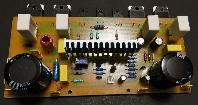
The power supply voltage for IC1 is derived from the main supply rails thru R17, D1, C8 and C9 for the negative voltage and R20, D2, C10 and C11 for the positive voltage. The blue heatsink for Q3/Q4 as seen on picture was from an old Pentium CPU cooler cut into half.
Now if you decide to build Project4, then put together the printed circuit assembly (PCA), i.e. fabricate and populate the PCB. A PCB layout and Project4 BOM are provided for free, as is, no warranty.
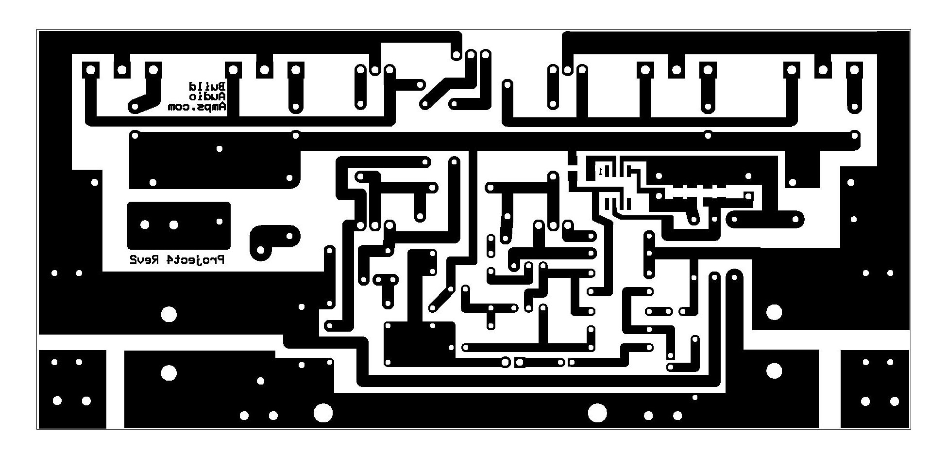 Bottom Copper Layer of PCB
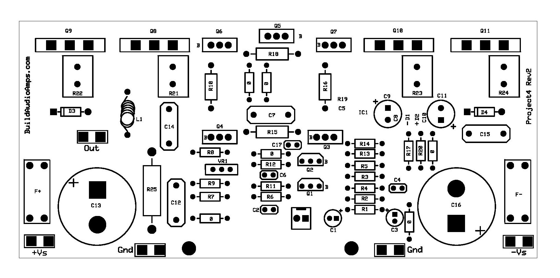
Silkscreen Parts Placement Layer of PCB
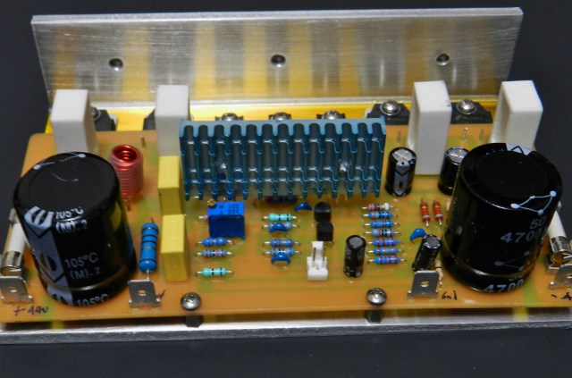
Project 4 installed on a thick aluminum-mounting bracket that can be attach to an extruded heatsink.
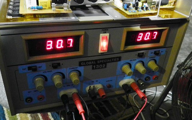
If you have decided to build and completed the PCB assembly, you have to do some testing first. Adjust trim pot VR1 fully clockwise until you hear it clicks. Install a shorting shunt or jumper at the input headers. Remove F+ fuse and replace it with a DMM set at the milliammeter function. Do not connect any load at the output but a DMM adjusted to the millivoltmeter function. I will be using a ±30VDC power supply to test this project. Here comes the moment of truth! Switch the power ON to whatever power supply you are using.
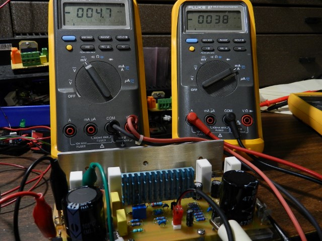
Normally the DMM will read about 4.7mV or less at the output with respect to ground, other than that power OFF immediately and recheck project. If reading is within 4.7mV proceed to the next step. The milliammeter should read about 30mA, if lower reading is obtained adjust VR1. If a higher reading is obtained and it cannot be adjusted power OFF immediately and recheck your work. Measure the voltages across D1 and D2 or at R17 and R20 with respect to ground, you should read from ±8VDC to ±15VDC.
If everything goes well, it is time to listen to some music. In my opinion the sound quality of this project, if matched with a good pre amp, does not disappoint. Enjoy!
![]()